Control apparatus for internal combustion engine

a control apparatus and internal combustion engine technology, applied in the direction of electric control, combustion engines, machines/engines, etc., can solve the problems of pre-ignition, knocking, etc., and achieve the effect of suppressing the risk of knocking, reducing the time, and preventing knocking

Active Publication Date: 2007-10-02
TOYOTA JIDOSHA KK
View PDF16 Cites 35 Cited by
  • Summary
  • Abstract
  • Description
  • Claims
  • Application Information

AI Technical Summary

Benefits of technology

[0011]The present invention has been made to solve the above-described problems. An object of the present invention is to ensure smooth startup of an internal combustion engine provided with a first fuel injection mechanism (in-cylinder injector) for injecting fuel into a cylinder and a second fuel injection mechanism (intake manifold injector) for injecting fuel into an intake manifold and / or an intake port, by preventing occurrence of pre-ignition and knocking.
[0029]According to this control apparatus for an internal combustion engine, the risk of knocking can be detected efficiently by using outputs of the sensors for measuring the coolant temperature and the intake air temperature that are normally provided in the internal combustion engine.

Problems solved by technology

At the time of engine startup during the engine cold state, however, the residual fuel within the cylinder due to fuel leakage from the in-cylinder injector while the operation of the internal combustion engine is being stopped, for example, may cause pre-ignition where the fuel ignites prior to an ignition timing because of the compression operation when the piston starts operation.
Further, at the time of engine startup during the engine warm state, knocking may occur due to an excessively high temperature inside the combustion chamber.

Method used


Image

  • Control apparatus for internal combustion engine
  • Control apparatus for internal combustion engine
  • Control apparatus for internal combustion engine

Examples


first embodiment

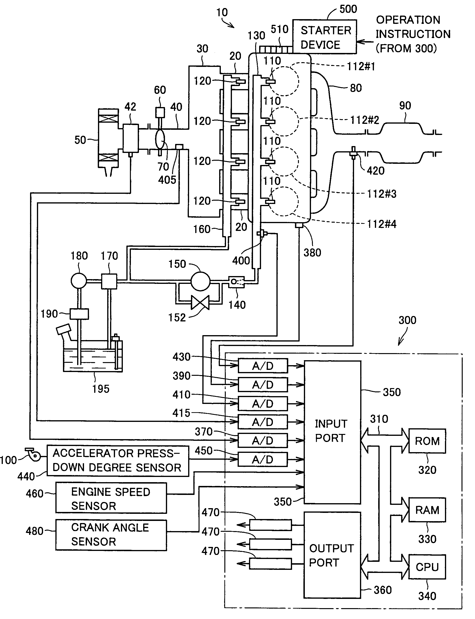
[0040]FIG. 1 is a schematic configuration diagram of an engine system that is controlled by an engine ECU (Electronic Control Unit) implementing the control apparatus for an internal combustion engine according to embodiments of the present invention. Although an in-line 4-cylinder gasoline engine is shown in FIG. 1, application of the present invention is not restricted to the engine shown.

[0041]As shown in FIG. 1, the engine (internal combustion engine) 10 is provided with four cylinders 112#1-112#4. Hereinafter, cylinders 112#1-112#4 may collectively be referred to as cylinder 112 or cylinders 112.

[0042]Cylinders 112 are connected via corresponding intake manifolds 20 to a common surge tank 30. Surge tank 30 is connected via an intake duct 40 to an air cleaner 50. In intake duct 40, an airflow meter 42 and a throttle valve 70, which is driven by an electric motor 60, are disposed. Throttle valve 70 has its degree of opening controlled based on an output signal of an engine ECU 30...

second embodiment

[0087]In the second embodiment of the present invention, startup-time fuel injection control in the engine system shown in FIG. 1 for ensuring smooth startup of the engine by preventing occurrence of knocking during the engine warm state will be described.

[0088]FIG. 7 is a flowchart illustrating startup-time fuel injection control during the engine warm state according to the second embodiment of the present invention. The startup-time fuel injection control shown in FIG. 7 is also carried out by activation of a program prestored in engine ECU 300.

[0089]Referring to FIG. 7, steps S100 and S110 are identical to those shown in FIG. 6. When YES in step S110 (i.e., during the engine warm state), the following steps S220-S270 are carried out.

[0090]At the time of engine startup during the engine warm state, if fuel injection is carried out solely from intake manifold injector 120, in-cylinder injector 110 will be constantly exposed to high-temperature combustion gas, and the cooling effec...


PUM


Abstract

At the time of startup of an engine having an in-cylinder injector and an intake manifold injector, a risk of pre-ignition during the first-time compression stroke is determined based on a rotational angle of a crankshaft at the time of previous engine stop. When there is a high risk of pre-ignition, fuel injection from the in-cylinder injector having been set to make an air-fuel ratio within the combustion chamber become out of a range enabling combustion (to attain an over-rich condition) is carried out in addition to fuel injection from the intake manifold injector for normal engine startup. Pre-ignition is thus prevented, and smooth engine startup is ensured.

Description

[0001]This nonprovisional application is based on Japanese Patent Application No. 2005-079258 filed with the Japan Patent Office on Mar. 18, 2005, the entire contents of which are hereby incorporated by reference.BACKGROUND OF THE INVENTION[0002]1. Field of the Invention[0003]The present invention relates to a control apparatus for an internal combustion engine, and more particularly to fuel injection control at the time of startup of an internal combustion engine provided with a first fuel injection mechanism (in-cylinder injector) for injecting fuel into a cylinder (into a combustion chamber) and a second fuel injection mechanism (intake manifold injector) for injecting fuel into an intake manifold and / or an intake port.[0004]2. Description of the Background Art[0005]An internal combustion engine having an in-cylinder injector for injecting fuel directly into a combustion chamber and an intake manifold injector for injecting fuel into an intake port (intake manifold) of each cylin...

Claims


Application Information

Patent Timeline
Patent Type & Authority Patents(United States)
IPC IPC(8): F02D41/30F02D41/06
CPCF02D35/027F02D41/3094F02D41/062F02D2041/1412
Inventor MIYAZAKI, KAZUMAKINOSE, KENICHI
Owner TOYOTA JIDOSHA KK
Why Eureka
Try Eureka