Distance measuring device and image pickup device

A technology of distance measuring device and camera element, which is applied in the direction of measuring device, focusing device, measuring distance, etc., which can solve the problems of low degree of freedom and distance measurement, and achieve the effect of improving the degree of freedom of setting

Active Publication Date: 2012-04-18
NIKON CORP
View PDF10 Cites 2 Cited by
  • Summary
  • Abstract
  • Description
  • Claims
  • Application Information

AI Technical Summary

Problems solved by technology

[0008] However, in the conventional device described above, in the case of performing pupil division by polarization to detect the phase difference, since the pupil division is performed by a fixed pupil shielding member, it is not possible to achieve the F value and the required performance of the lens. Consistent ranging, there is a problem of low degrees of freedom

Method used


Image

  • Distance measuring device and image pickup device
  • Distance measuring device and image pickup device
  • Distance measuring device and image pickup device

Examples


no. 1 approach

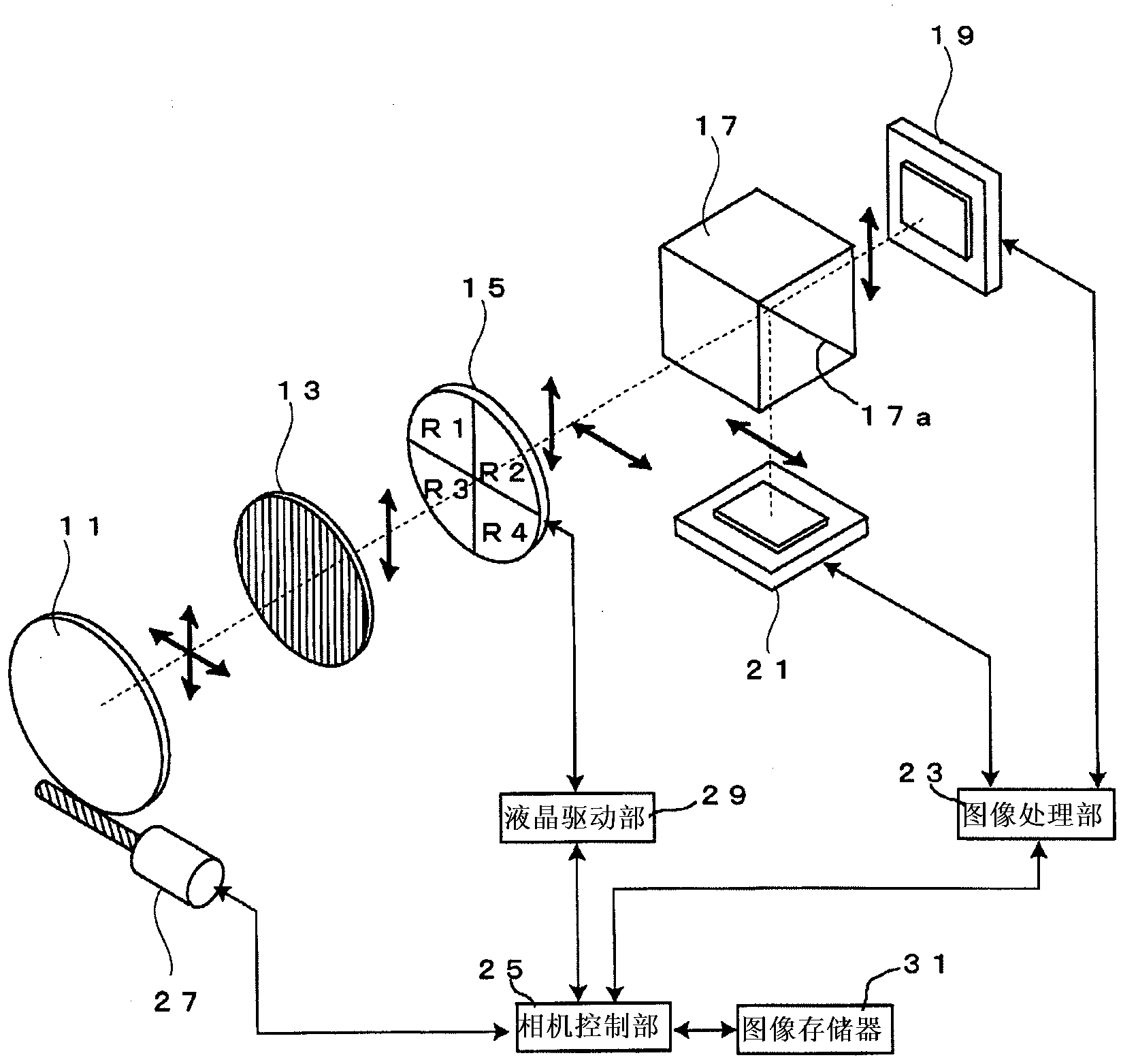
[0035] figure 1 The first embodiment of the distance measuring device of the present invention is shown. In this embodiment, the present invention is applied to an imaging device including a camera.

[0036] The imaging device includes: an objective lens 11, a polarizing element 13, a liquid crystal rotator 15, a polarization separation element 17, a first imaging element 19, a second imaging element 21, an image processing unit 23, a camera control unit 25, an AF driving mechanism 27, a liquid crystal driving Part 29, image memory 31.

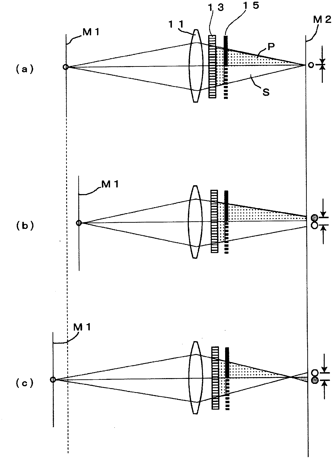
[0037] A polarizing element 13 is provided at the pupil position of the objective lens 11 . The polarizing element 13 is constituted by a polarizing filter for aligning the polarization axis of the light from the objective lens 11 to, for example, P-polarized light.

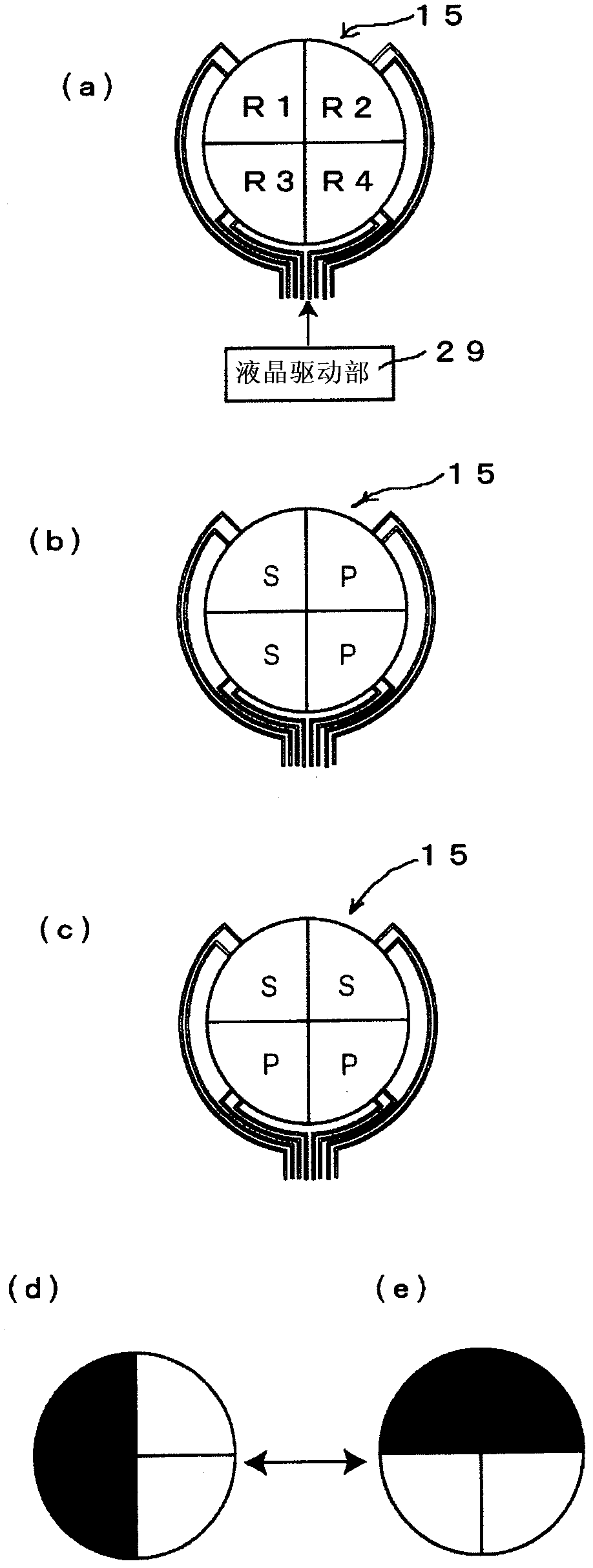
[0038] The liquid crystal rotator 15 electrically changes the polarization axis of light. Such as figure 2 As shown in (a), the light transmission surface of the liquid cry...

no. 2 approach

[0050] Figure 4 It shows the second embodiment of the distance measuring device of the present invention. In this embodiment, the present invention is applied to an imaging device including a camera. In addition, in this embodiment, the same code|symbol is attached|subjected to the same element as 1st Embodiment, and detailed description is abbreviate|omitted.

[0051] The imaging device includes: an objective lens 11, a liquid crystal shutter 33, a pupil splitting liquid crystal rotator 35, a polarization separation element 17, a first imaging element 19, a second imaging element 21, an image processing unit 23, a camera control unit 25, and an AF drive mechanism 27 , a liquid crystal drive unit 29 , and an image memory 31 .

[0052] A liquid crystal shutter 33 is provided at the pupil position of the objective lens 11 . The liquid crystal shutter 33 includes a first polarizing element 37 , a pupil mask liquid crystal rotator 39 , and a second polarizing element 41 .

[...

no. 3 approach

[0072] Figure 9 A third embodiment of the imaging device of the present invention is shown.

[0073] In this embodiment, the drive area of ​​the pupil mask liquid crystal rotator 39A is finely divided.

[0074] Such as Figure 9 As shown in (a), the pupil-mask liquid crystal rotator 39A finely divides the drive area like a general dot-matrix liquid crystal display. More functions can be realized by driving the fine driving area according to the situation.

[0075] (1) if Figure 9 As shown in (b), by setting the same transmission region as a simple fixed pattern, it is possible to function as a pupil mask.

[0076] (2) if Figure 9 As shown in (c), at the time of exposure, the transmissive region is provided as a concentric circle with respect to the optical axis, and can function as a diaphragm.

[0077] (3) if Figure 9 As shown in (d), by adjusting the amount of transmission in the transmission area together with the aperture drive, it is possible to adjust the amou...


PUM


Abstract

A distance measuring device comprises a polarization element arranged in a plane conjugate with a pupil of an objective lens, a rotator which rotates the polarization axis of light transmitted through the polarization element, a polarized light splitting element which splits the light transmitted through the rotator into a first light flux and a second light flux, a first image pickup element which captures a first image formed by the first light flux, a second image pickup element which captures a second image formed by the second light flux, and a focus detection means for detecting a focus state on the basis of a relative deviation between the first image and the second image, for the same area of an object.

Description

technical field [0001] The present invention relates to a distance measuring device and an imaging device. Background technique [0002] Conventionally, there is known an optical device that performs focus detection of an imaging optical system by a pupil division method (for example, refer to Patent Document 1). [0003] In the above device, an electro-optical element combining a diffraction grating and a liquid crystal is inserted into the pupil plane of the imaging optical system to deflect light passing through different regions in the exit pupil to different directions. Then, the respective light beams are formed into different regions of the imaging element that captures the image of the imaging optical system, and phase difference AF is performed based on the imaging data. [0004] prior art literature [0005] patent documents [0006] Patent Document 1: Japanese Unexamined Patent Publication No. 2006-106435 Contents of the invention [0007] The problem to be ...

Claims


Application Information

Patent Timeline
Patent Type & Authority Applications(China)
IPC IPC(8): G03B13/36G01C3/06G02B7/34H04N5/232
CPCG02B7/28G01C3/08G03B13/36H04N5/23212G02B27/286G03B13/20G02B7/343H04N23/672G01S7/499G01S17/86G01S17/08
Inventor 荻野泰
Owner NIKON CORP
Why Eureka
Try Eureka