

Motor-assisted bicycle
An electric power assist and bicycle technology, which is applied to bicycle frames, bicycle accessories, vehicle parts, etc., can solve the problem of not being able to arouse the attention of pedestrians around the vehicle, and achieve the effect of reducing the number of parts, improving the freedom of setting, and ensuring the installation space.
- Summary
- Abstract
- Description
- Claims
- Application Information
AI Technical Summary
Problems solved by technology
Method used
Image

Examples
no. 1 example
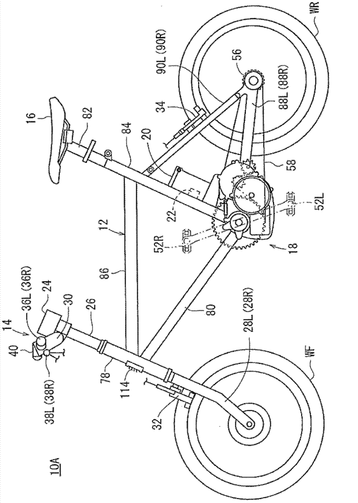
[0067] Such as figure 1 As shown, the electric power-assisted bicycle 10A is constructed based on a body frame 12, and has: a front wheel WF that is a steered wheel, a rear wheel WR that is a drive wheel, a control unit 14 for manipulating the front wheel WF, and a seat for a rider (not shown). seat 16 , a drive mechanism 18 for driving the rear wheel WR, a battery unit 20 provided on the vehicle body frame 12 , an alarm buzzer 22 provided on the battery unit 20 , and a display unit 24 provided on the operating unit 14 . In addition, the structure of the vehicle body frame 12 will be described retroactively.
[0068] The steering unit 14 has a steering shaft 26 , a pair of front forks 28L, 28R extending from the lower end of the steering shaft 26 to pivotally support the front wheel WF, and a handlebar 30 provided on the upper portion of the steering shaft 26 .
[0069] The front forks 28L and 28R are provided with cantilever brakes 32 for front wheels that stop the rotation ...
no. 2 example
[0126] Refer to the side below Figure 12 and Figure 13 An electric assist bicycle 10B according to a second embodiment of the present invention will be described. In the second embodiment, the same reference numerals are assigned to the same structural elements as those of the above-mentioned embodiment, and detailed description thereof will be omitted. The same applies to the third to fifth embodiments described later.
[0127] Such as Figure 12 As shown, in the electric power-assisted bicycle 10B of this embodiment, the battery unit 232 is provided at a portion of the outer peripheral surface of the upper tube 86 that faces the down tube 80 . An inlet 234 for allowing the alarm sound of the alarm buzzer 22 to enter inside is formed in the upper pipe 86 .
[0128] Such as Figure 13 As shown, the battery unit 232 has a bottomed cylindrical battery case (case member) 236 , a bottomed cylindrical key case 238 disposed on the battery case 236 , and can be installed in th...
no. 3 example
[0137] Refer to the side below Figure 14 An electric assist bicycle 10C according to a third embodiment of the present invention will be described.
[0138] Such as Figure 14 As shown, in the electric power-assisted bicycle 10C of this embodiment, the battery unit 232 described in the second embodiment is provided at a portion of the outer peripheral surface of the down tube 80 facing the upper tube 86 . An inlet 274 for allowing the alarm sound of the alarm buzzer 22 to enter inside is formed in the down pipe 80 .
[0139] as from Figure 14 As is known, the sixth sound insulating member 278 is provided in the seat tube 84 to close the opening on the other end side of the down tube 80 . The third sound insulating member 106 is omitted.
[0140]According to the electric assist bicycle 10C of this embodiment, the alarm sound emitted from the alarm buzzer 22 is introduced into the down tube 80 through the inlet port 274 and transmitted to the head tube 78 . At this time, ...
PUM
 Abstract
Description
Claims
Application Information