image forming device

An image and object technology, applied in the field of image forming devices, can solve problems such as missing maintenance time

Inactive Publication Date: 2018-04-13
KYOCERA DOCUMENT SOLUTIONS INC
View PDF4 Cites 0 Cited by
  • Summary
  • Abstract
  • Description
  • Claims
  • Application Information

AI Technical Summary

Problems solved by technology

Therefore, with the above-mentioned input device, there is a risk of missing a message that the maintenance time is approaching, and the above-mentioned problem cannot be solved.

Method used


Image

  • image forming device
  • image forming device
  • image forming device

Examples


Embodiment Construction

[0026] Below, use Figure 1 to Figure 12 , the embodiment of the present invention will be described. Hereinafter, the all-in-one machine 100 is taken as an example for description. Each element described in this embodiment, such as a structure and arrangement|positioning, is an example for illustration, and does not limit the scope of invention. The all-in-one machine 100 corresponds to an "image forming device".

[0027] (Overall structure of the multifunction machine 100)

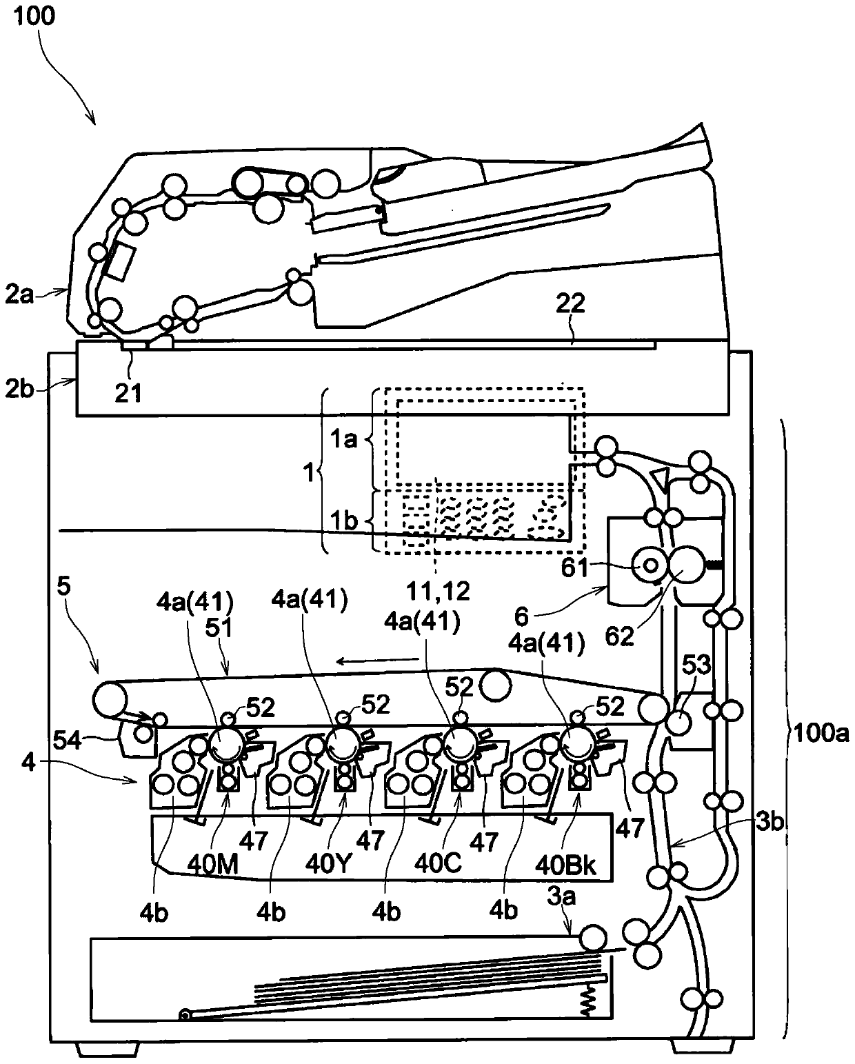
[0028] Next, use figure 1 , the all-in-one machine 100 according to the embodiment will be described. figure 1 is a diagram showing an example of the multifunctional machine 100 .

[0029] Such as figure 1 As shown, the all-in-one machine 100 includes: an operation panel 1, a document conveying unit 2a, and an image reading unit 2b. The document conveyance unit 2 a conveys the document to the contact glass 21 for conveyance and reading. Furthermore, the image reading unit 2b reads an image formed...


PUM


Abstract

An image forming apparatus according to the present invention includes an operation panel including a display unit displaying buttons, a touch panel unit, a plurality of piezoelectric elements, and a panel control unit. The image forming apparatus further includes a vibration control unit and a determination unit. The vibration control unit outputs a drive signal to the piezoelectric element, and the drive signal vibrates the touch panel unit. The judging unit judges the inspection object based on the maintenance object to be replaced or replenished and the maintenance time, and the inspection object is an object whose maintenance time is within a preset period among the plurality of maintenance objects. The above-mentioned vibration control unit vibrates the touch panel unit and the piezoelectric element under normal vibration conditions when the button operation is performed in the state where the inspection object does not exist, and the operation of the preset button is controlled in the state where the inspection object exists. When executed, the touch panel portion and the piezoelectric element are vibrated under vibration conditions different from normal vibration conditions.

Description

technical field [0001] The present invention relates to an image forming apparatus including a display unit, a touch panel unit, and a piezoelectric element for vibrating the touch panel unit. Background technique [0002] In recent years, piezoelectric elements have been provided in input devices (for example, portable information terminals) on which a display portion and a touch panel portion are superimposed and which accept operations and inputs. When an input operation of touching the display position of the button is performed, a voltage is applied to the piezoelectric element to displace (deform) the piezoelectric element. Then, based on the displaced vibration, the user's sense of touch is stimulated. By using a piezoelectric element, it is possible to give the user a click feeling like operating a hardware button. [0003] An example of the above technique has been invented. Specifically, an input device having a panel displacement element (piezoelectric actuator...

Claims


Application Information

Patent Timeline
Patent Type & Authority Patents(China)
IPC IPC(8): G06F3/041G06F3/048G06F3/0488
CPCG03G15/5016
Inventor 田中容子
Owner KYOCERA DOCUMENT SOLUTIONS INC
Why Eureka
Try Eureka