Eureka AIR delivers breakthrough ideas for toughest innovation challenges, trusted by R&D personnel around the world.

Drive apparatus for sewing machine

A technology for driving devices and sewing machines, which is applied in the direction of sewing machine control devices, sewing machine components, sewing equipment, etc., and can solve the problems of being unable to prevent abnormal high-speed rotation of sewing machine motors and reducing energy efficiency

Inactive Publication Date: 2018-06-26
AISIN SEIKI KK
View PDF8 Cites 0 Cited by
  • Summary
  • Abstract
  • Description
  • Claims
  • Application Information

AI Technical Summary

Problems solved by technology

[0004] However, in the above-mentioned driving device for the sewing machine, since the resistance of the cut-off circuit is connected in parallel with the drive start switch, the cut-off circuit can only detect the short circuit of the switching element when the foot controller is not operated.
Therefore, if the user operates the foot controller, even if the switch element is short-circuited, it is impossible to prevent the sewing machine motor from rotating at an abnormal high speed.
In addition, in the above-mentioned driving device of the sewing machine, even when the drive start switch is turned off, a small current flows to the resistance connected in parallel with the drive start switch, so the energy efficiency is lowered.

Method used


Image

  • Drive apparatus for sewing machine
  • Drive apparatus for sewing machine
  • Drive apparatus for sewing machine

Examples


Embodiment Construction

[0025] Modes for carrying out the present invention will be described using examples.

[0026] 【Example】

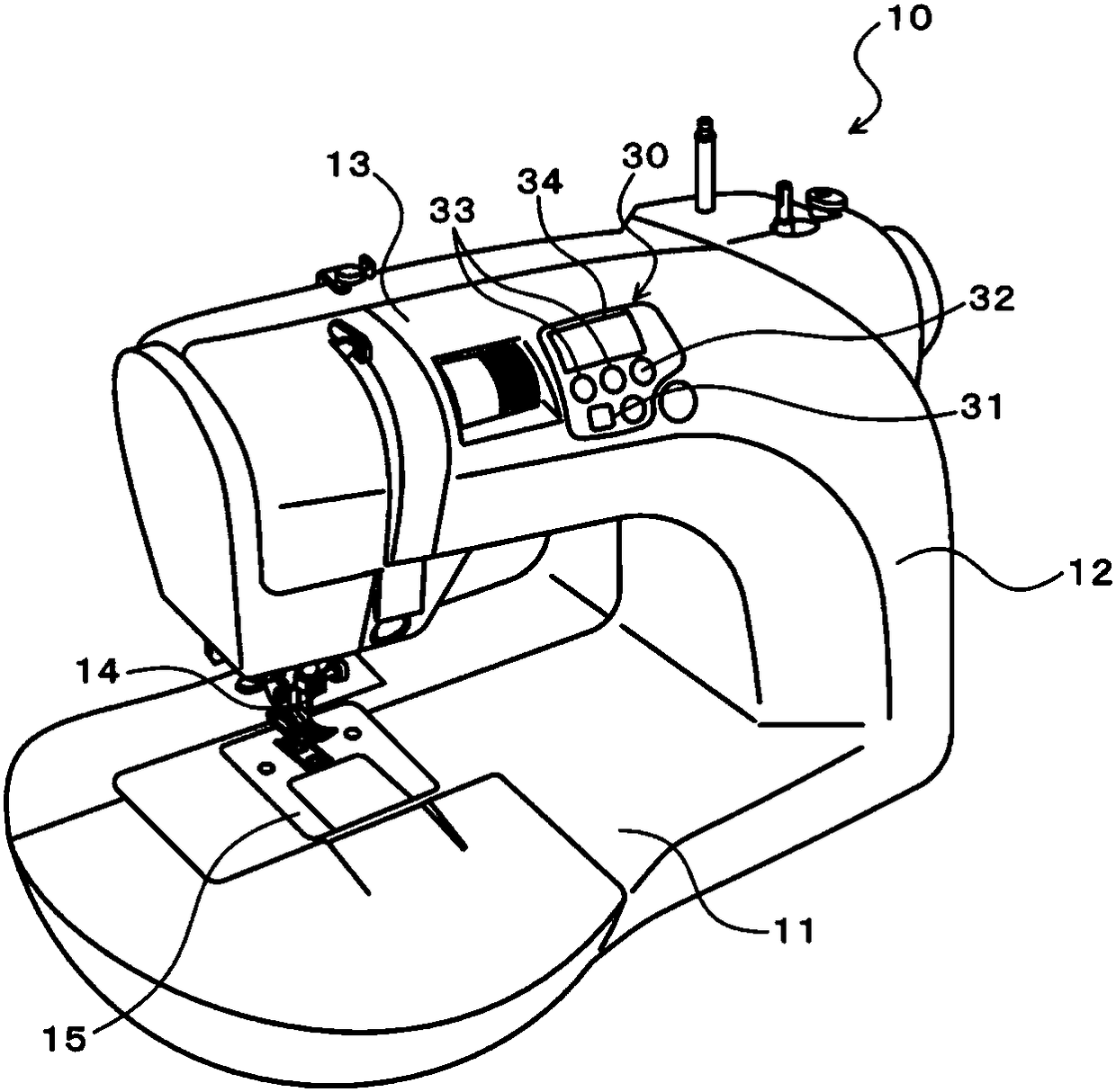
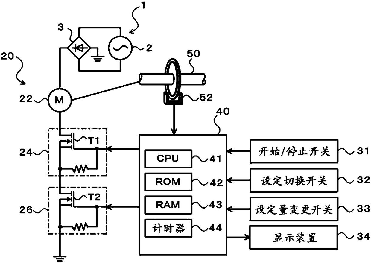
[0027] figure 1 is a configuration diagram showing a schematic configuration of the sewing machine 10, figure 2 It is an explanatory diagram showing the electrical connection relationship of the driving device 20 of the sewing machine. As shown in the figure, the sewing machine 10 is composed of a machine base 11, a body 12 erected from the right end of the machine base 11, and a head 13 protruding from the upper end of the body 12 parallel to the machine base 11 to the left.

[0028] A sewing needle 14 is provided at the tip end of the machine head 13 so as to protrude downward. The sewing needle 14 is connected to an upper shaft 50 (see figure 2 )link. On the upper shaft 50, a DC motor 22 is connected via a transmission mechanism (see figure 2 ), the upper shaft 50 is driven by the DC motor 22 to rotate, and the rotary motion of the upper shaft 50 is converted ...


PUM


Abstract

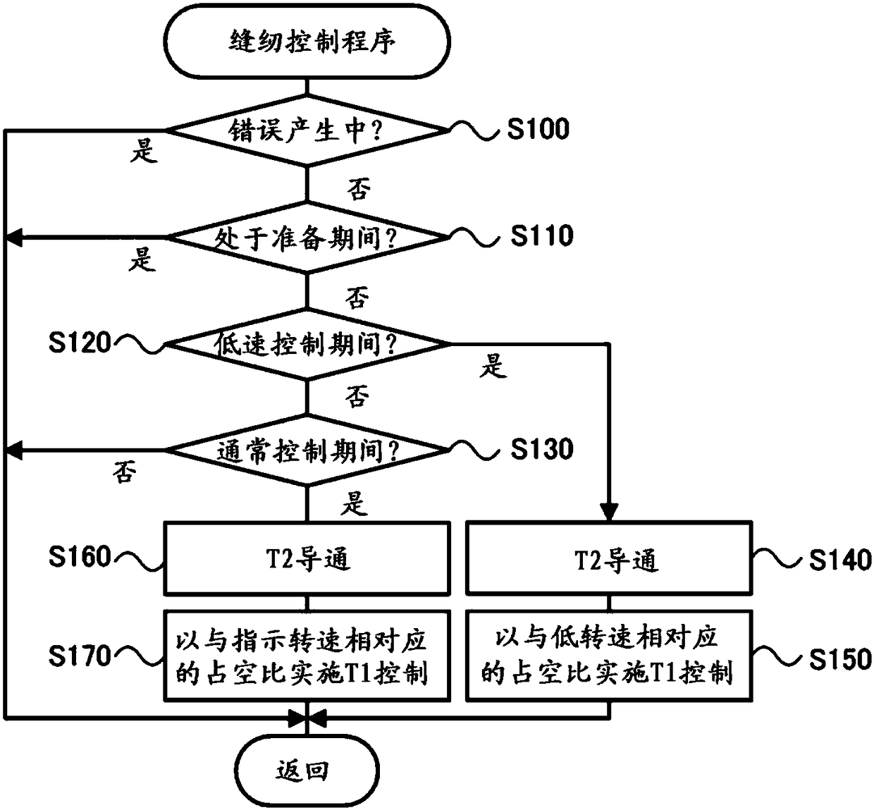
The invention provides a drive apparatus for a sewing machine. The drive apparatus for a sewing machine properly determines the fault of the drive circuit and inhibits abnormal driving of a sewing needle, and includes: a motor, a rotation speed measuring device, a control device, a first drive circuit including a first switching element, and a second drive circuit including a second switching element, wherein the first switching element and the second switching element are connected to a power supply and the motor in series; when the control device is indicated about the sewing motion, the control device performs a sewing control to control the second drive circuit to turn on the second switching element and control the first drive circuit, so as to enable the motor to be driven at a target rotation speed through the switching motion of the first switching element; and in a predetermined period during which the sewing control is not executed, the control device performs control to turnon one switching element and turn off the other switching element, and then determines rotation of the motor based on the rotation speed measuring device, so as to determine a short circuit failure of the first drive circuit or the second drive circuit.

Description

technical field [0001] The present invention relates to a drive device for a sewing machine, and more specifically, to a drive device for a sewing machine including a motor, a first drive circuit, a second drive circuit, a rotational speed detection device, and a control device. Background technique [0002] Conventionally, as a driving device for such a sewing machine, the following driving device has been proposed, which includes: a driving start switch provided in a driving circuit of a sewing machine motor; a speed adjusting circuit having a speed adjusting variable resistor and a A switching element that cooperates with a variable resistor; a cutoff circuit that cuts off a drive circuit when the switching element is short-circuited (for example, see Patent Document 1). The cutoff circuit has: a thermal fuse connected in series to the driving circuit of the sewing machine; and a resistor provided close to the thermal fuse and connected in parallel to the drive start swit...

Claims


Application Information

Patent Timeline
Patent Type & Authority Applications(China)
IPC IPC(8): D05B69/00D05B69/36
CPCD05B69/00D05B69/36D05B69/18
Inventor 安藤孝树
Owner AISIN SEIKI KK
Why Eureka
Eureka Blog
Learn More