Elevator device

A technology of equipment and elevators, which is applied in the direction of elevators, elevators, transportation and packaging in buildings, can solve the problems of reducing the size of driving pulleys, and achieve the effect of increasing the degree of freedom of setting, utilizing space, and increasing the service life

Active Publication Date: 2009-05-06
HITACHI LTD +1
View PDF1 Cites 3 Cited by
  • Summary
  • Abstract
  • Description
  • Claims
  • Application Information

AI Technical Summary

Problems solved by technology

[0006] But, in above-mentioned prior art, its purpose just will dwindle the size of drive pulley, and the aspect that does not improve the overall performance of elevator is considered

Method used


Image

  • Elevator device
  • Elevator device
  • Elevator device

Examples


Embodiment Construction

[0036] Embodiments of the present invention will be described below with reference to the drawings.

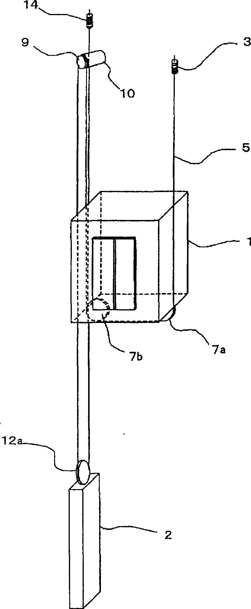
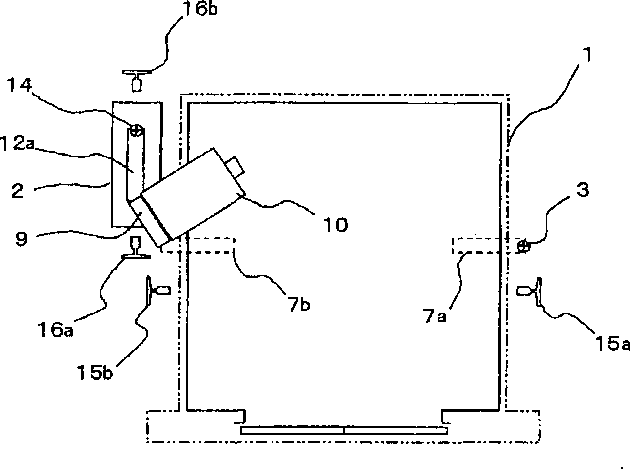
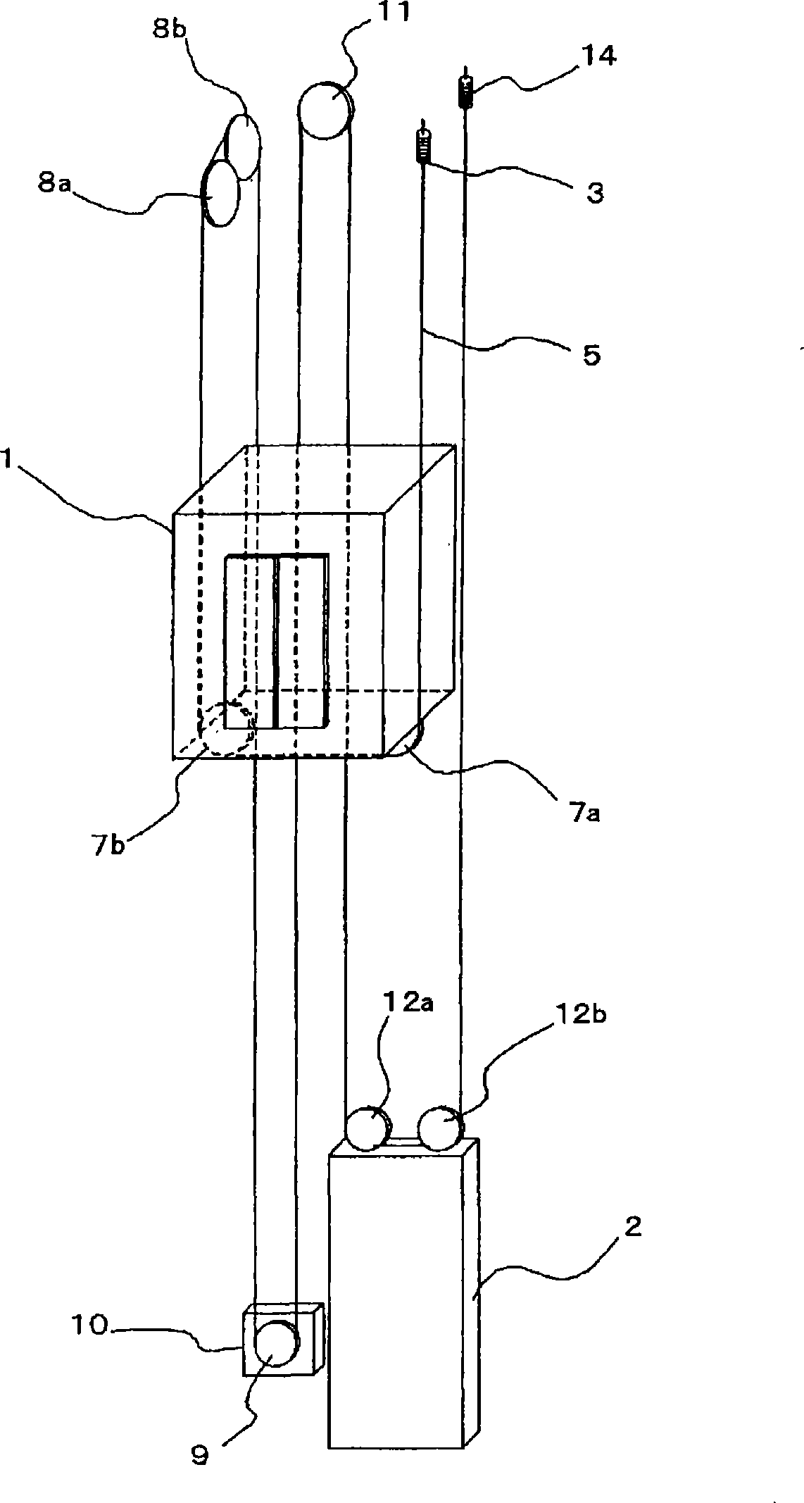
[0037] figure 1 It is a perspective view showing one embodiment of the elevator equipment of the present invention, figure 2 is viewed from above figure 1 when the top view, image 3 is a perspective view showing another embodiment of the elevator apparatus of the present invention, Figure 4 is viewed from above image 3 when the top view, Figure 5 It is a perspective view showing still another embodiment of the elevator equipment of the present invention, Figure 6 is viewed from above Figure 5 time top view.

[0038] exist figure 1 Among them, the elevator car side main rope fixing part 3 is arranged on the upper part of the side surface of the elevator car 1, and the main rope 5 is configured to extend downward from the elevator car side main rope fixing part 3, from the elevator The car sheave 7a extends through another elevator car sheave 7b, and reaches the ...


PUM


Abstract

An elevator device where a reduction in the lifetime of the main rope is kept as small as possible even if the diameter of the drive sheave is reduced. The elevator device uses a hoist (10(10A)) having the drive sheave (9) with the diameter not more than 29 times as large as the diameter of the main rope, and at least an elevator car (1) and counterbalance weight (2) have rope sheaves (7a, 7b, 11 (12a, 12b)). The diameters of the rope sheaves (7a, 7b, 11 (12a, 12b)) are set greater than the diameter of the drive sheave (9).

Description

technical field [0001] The invention relates to an elevator installation having an elevator car which is raised and lowered in a hoistway. Background technique [0002] In the existing elevator equipment, the elevator car and the counterweight are connected by the main sling, and the main sling is wound on the driving pulley through the steering sheave, the elevator car and the sheave on the The driving pulley makes the elevator car and the counterweight go up and down. In the above-mentioned existing elevator equipment, in order to reduce the damage caused by the frictional drive to the main rope and reduce the bending resistance, etc., the general method is to make the driving pulley and the rope The diameter of the wheel is set to be 40 times or more the diameter of the main hanger. However, in recent years, a main hanger with improved bending performance has been developed by using synthetic fibers such as aramid and Kevlar. Rope, and the main hanger with longer service...

Claims


Application Information

Patent Timeline
Patent Type & Authority Applications(China)
IPC IPC(8): B66B7/06B66B11/08
CPCB66B11/008
Inventor 萩谷知文西野克典
Owner HITACHI LTD
Why Eureka
Try Eureka