Auxiliary assembly for reducing unwanted movement of a hoist rope

a technology of unwanted movement and auxiliary assembly, which is applied in the direction of hoisting equipment, mechanical machines/dredgers, elevators, etc., can solve the problems of broken wires in the outside layers of the rope, stress in the hoist rope, and wire breakage, so as to reduce the vibration the effect of limiting the vibration of the rope span and significantly reducing the stress of the hoist rop

Active Publication Date: 2006-04-11
JOY GLOBAL SURFACE MINING INC
View PDF6 Cites 28 Cited by
  • Summary
  • Abstract
  • Description
  • Claims
  • Application Information

AI Technical Summary

Benefits of technology

[0008]One of the principle features of the invention is the provision of an auxiliary hoist rope sheave assembly that supports the hoist rope near the mid-span of the boom in order to limit vibration of the rope span. By limiting the hoist rope vibration, rope bending stresses due to vibration are significantly reduced.
[0009]Another of the principle features of the invention is the providing of an improved electric mining shovel with increased hoist rope life, thus increasing the time between hoist rope change outs without the more typical and very costly approaches of increasing rope diameter or the rope winding drum diameters.
[0010]Another of the principle features of the invention is to reduce the length of the typical electric mining shovel rope span, and thus reduce the amount of vibration typically seen by the rope. By providing a support in the middle of the span, the typical span is replaced by two shorter segments.
[0011]The assembly includes a welded, tubular frame that is pin-mounted to the shovel boom structure. Housed within this frame are two steel shafts. The lower shaft houses two dual-grooved sheaves that fleet side-to-side as the hoist ropes follow the drum grooving. The upper shaft houses two split, nylon rollers that help to contain the ropes within the sheaves and to keep them from jumping out of the grooves. Two adjustable, turnbuckle-style, struts are employed to support the frame and to provide a means of adjusting the height of the sheaves. Changing the height of the sheaves allows for adjusting the amount of deflection of the hoist ropes from the direct line-of-sight path from the drum to the boom point sheave. The mechanism provides intimate contact with the hoist ropes and has the capability to preload or not to preload the rope span.

Problems solved by technology

Further, electric mining shovels frequently encounter situations that result in the dipper impacting something that causes stress in the hoist rope.
The repeated effect of these bending stresses due to the vibration of the rope span can fatigue the rope and eventually result in broken wires in the outside layers of the rope.
This bending fatigue in the wire rope results from rubbing between the wires in the rope main strands and the outer wires of the center strand.
This rubbing eventually causes the wires to break.
If a significant amount of the wires break, there may not be enough strength remaining to support the applied load.
This can result in rope failure.
Because many of the wire breaks may occur inside the wire rope and are unseen and difficult to detect by other means, the failure can come as a surprise.
Some of these may be because the ropes are damaged due to impact or abrasion near the dipper; there is reduced rope diameter due to wear or loss of core support; there is corrosion near the end supports of the rope; or there are a number of broken wires in the outer layers of the rope.
This increase in diameter can help to lengthen rope life, but the increase in diameter has limitations.
Small increases in diameter, ⅛ inch (0.3 cm) or less, can sometimes be accommodated with the existing drum and sheave grooving, but this small increase alone will likely not have a profound effect on rope life.
Larger increases require larger drum grooving and possibly increased groove pitch spacing.

Method used


Image

  • Auxiliary assembly for reducing unwanted movement of a hoist rope
  • Auxiliary assembly for reducing unwanted movement of a hoist rope
  • Auxiliary assembly for reducing unwanted movement of a hoist rope

Examples


Embodiment Construction

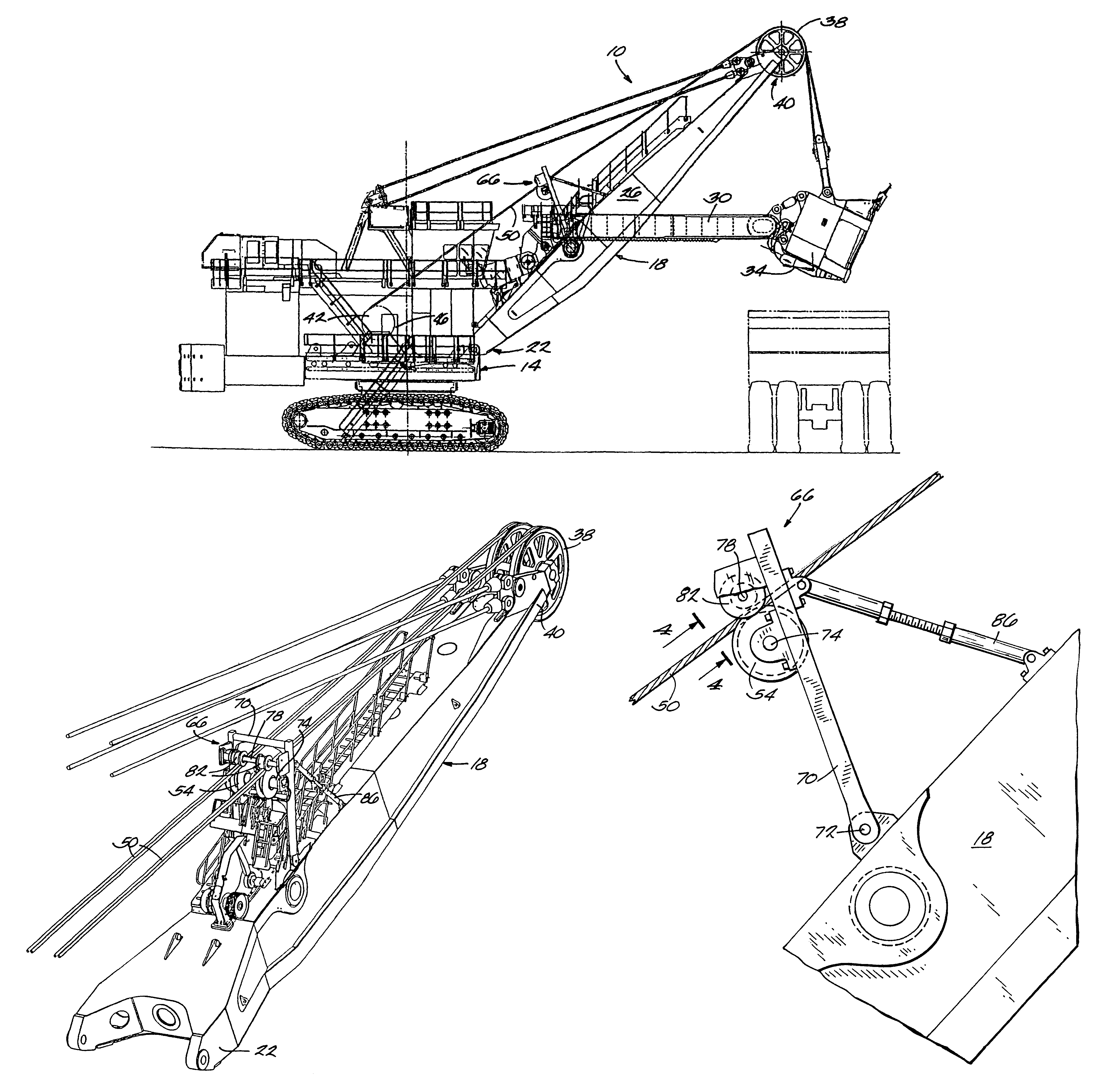
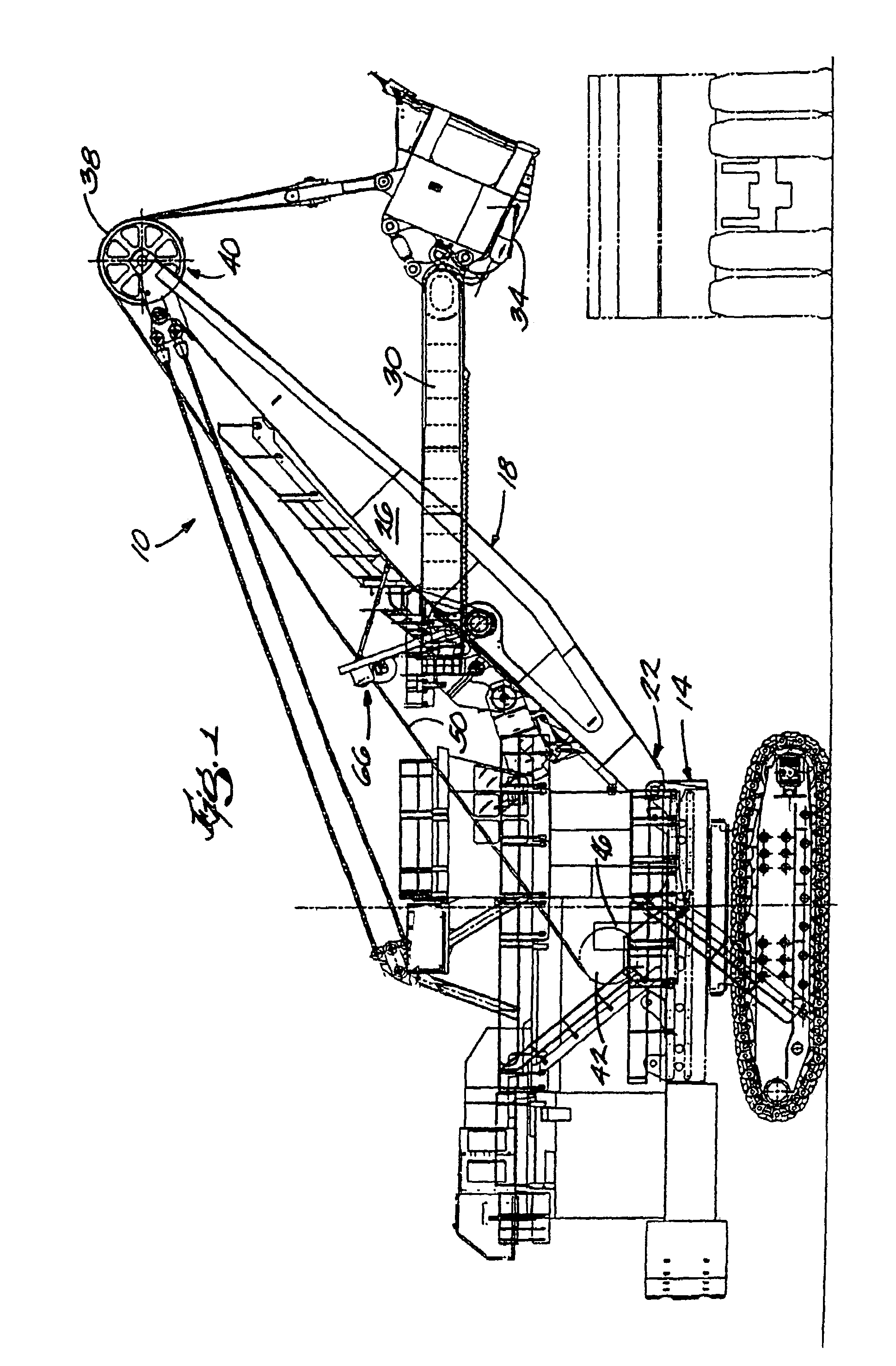
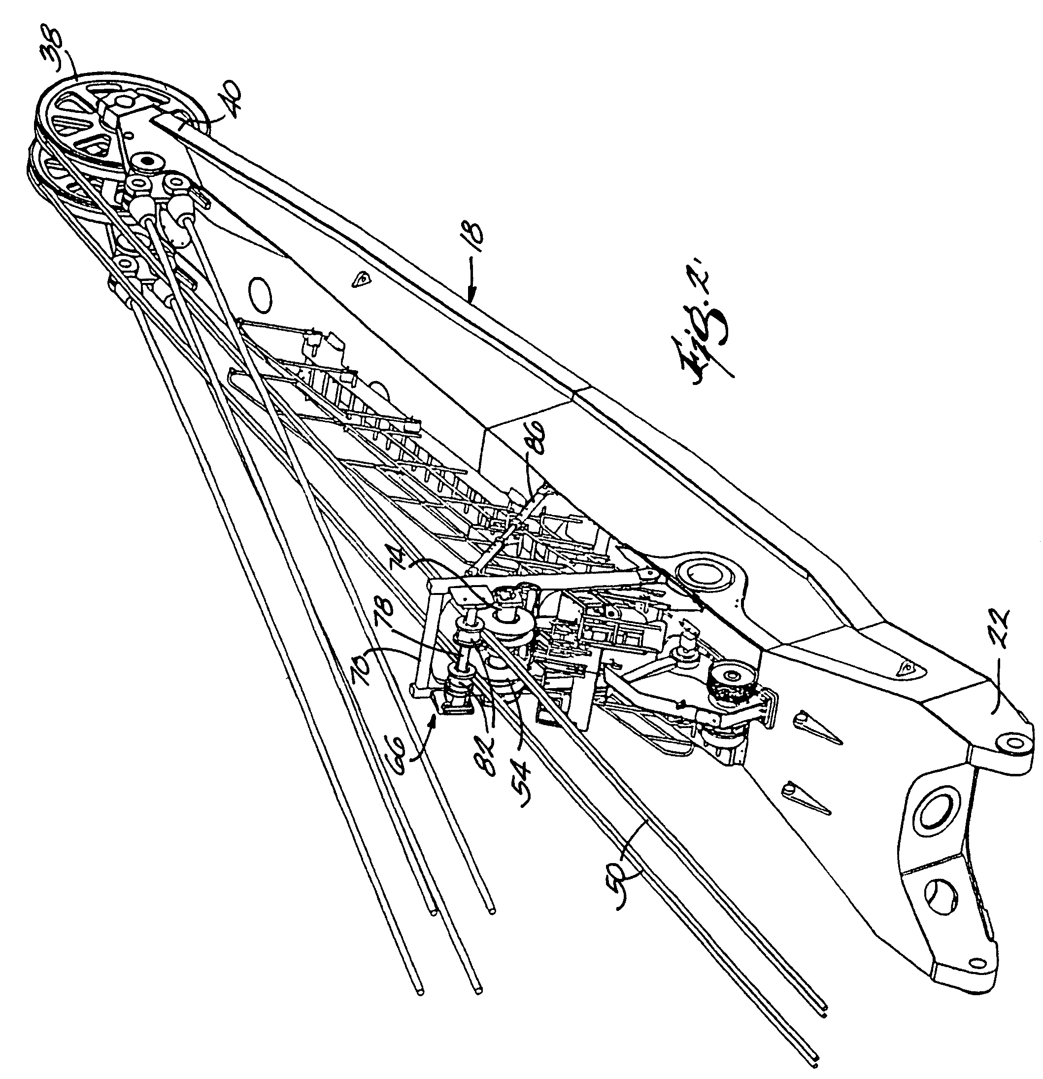
[0017]As illustrated in the drawings, this invention provides mining equipment in the form of an electric shovel 10 including a revolving frame 14, and a boom 18 having two ends, with one end 22 attached to the revolving frame 14. In other embodiments, other equipment, such as a dragline (not shown) could be used. The boom 18 has a mid point 26 between the two ends. The shovel 10 also includes a handle 30 movable mounted on the boom 18, a dipper 34 attached to the end of the handle 30, and a boom point sheave 38 rotatably mounted near the other end 40 of the boom 18.

[0018]The shovel 10 further includes a hoist rope drum 42 mounted on the revolving frame 14, driven through a gearbox 46 attached to the revolving frame 14, and a hoist rope 50 that extends from the hoist rope drum 42 along the boom 18 and over the hoist sheave 54. More particularly, as shown in FIG. 2, there are two pairs of two hoist ropes 50. The part of the hoist rope 50 that extends from the hoist rope drum 42 to th...


PUM


Abstract

An auxiliary hoist sheave assembly comprising a sheave support frame, a mechanism for mounting the sheave support frame to a boom, a lower sheave shaft mounted on the sheave support frame, and a grooved hoist sheave, rotatably supported by and slidable along the lower sheave shaft, the hoist sheave being in contact with a hoist rope, and the hoist sheave fleeting side to side along the lower sheave shaft as the hoist rope follows the hoist drum.

Description

BACKGROUND OF THE INVENTION[0001]This invention relates to mining equipment utilizing hoist or wire rope or ropes and, more particularly, to auxiliary assemblies for reducing unwanted movement of a hoist rope of a mining machine.BACKGROUND OF THE INVENTION[0002]Large mining machines accomplish the task of digging through a bank by suspending a bucket or dipper on steel hoist ropes that pass over steel sheaves mounted at the tip of a stationary boom. The ropes then connect to and wrap around a hoist drum mounted to the revolving frame structure. The hoist drum is motor driven through a gearbox attached to the revolving frame. Rotation of the drum in one direction hoists the dipper through the bank. Rotation of the drum in the opposite direction allows the dipper to be lowered.[0003]During both of these operations, but specifically while under heavy load during the digging / hoisting operation, the rope span between the hoist drum and boom point sheaves can move up or down or side to si...

Claims


Application Information

Patent Timeline
Patent Type & Authority Patents(United States)
IPC IPC(8): E02F5/02E02F9/14B66B7/12B66B15/04B66C13/04B66C13/10B66C23/66B66D1/36B66D3/08E02F3/30E02F3/358E02F3/36E02F3/46E02F3/58E21C29/14
CPCB66C23/66E02F3/36E02F3/304
Inventor SUZIK, JASON E.WEBER, THOMAS P.
Owner JOY GLOBAL SURFACE MINING INC
Why Eureka
Try Eureka