Light emissive display based on lightwave coupling

a technology of lightwave coupling and light emissive display, which is applied in the direction of waveguides, identification means, instruments, etc., to achieve the effect of reducing background luminance, high efficiency, and efficient outcoupling of emission

Active Publication Date: 2005-06-09
CINCINNATI UNIV OF +1
View PDF17 Cites 114 Cited by
  • Summary
  • Abstract
  • Description
  • Claims
  • Application Information

AI Technical Summary

Benefits of technology

[0008] The light emissive display technology of the invention uses a highly efficient lamp or LED technology and requires no polarizers or color filtering of white light. Furthermore, a light emissive display is provided that is inherently lambertian, or emissive, in nature such that the pixels are efficient in outcoupli

Problems solved by technology

Furthermore, the photoluminescent medium may be designed to emit light primarily and efficiently in the direction of the viewer only achieving greater than about 50 percent light outcoupling, which significantly exceeds conventional approaches that are generally lim

Method used


Image

  • Light emissive display based on lightwave coupling
  • Light emissive display based on lightwave coupling
  • Light emissive display based on lightwave coupling

Examples


example 1

[0101] A polymer binder (Ferro 75001 polyvinylbutyrolterpolymer PVB, binder) was mixed with about 1 percent to about 10 percent by volume solution of acetone and the maximum soluble concentration of BASF Lumogen 300 and BASF Lumogen 083 fluoropolymers to form a photoluminescent resin. The photoluminescent resin was doctor blade applied to a glass substrate and baked at 150° C. for 10 minutes to volatilize all solvents in order to form a solid gel layer. The photoluminescent layer was then bonded to DuPont Kapton tape film and pulled from the glass substrate it was formed on to create a usable film flexible film. The resulting photoluminescent film was placed on an acrylic waveguide propagating blue / violet light from a cold-cathode-fluorescent-lamp.

[0102] In regions where pressure was applied onto the photoluminescent layer onto the substrate, the photoluminescent layer brightly fluoresced. The photoluminescent layer was further pressed against the glass in several regions, opticall...

example 2

[0103] BASF Lumogen dyes were dissolved at maximum solubility in Acetone. BASF dye Lumogen 570 was used for blue emission, Lumogen 083 for green emission, and Lumogen 300 for red emission. This mixture was then added to and dissolved in acrylic beads in an airtight container. Once the mixture was completely dissolved, a non-volatile thinner of DuPont 8250 was added, mixed, and the acetone allowed to volatize over a period of 12 hours. This photoluminescent resin was then screen-printed onto an acrylic waveguide and baked at 120° C. for 15 minutes to remove the DuPont 8250, forming a hard and transparent photoluminescent layer. The waveguide was then mirrored using an Al adhesive tape and InGaN LEDs attached through apertures in the tape.

[0104] This signage form of an LWC display exhibited the following performance:

Waveguide Dimensions:about 2″× 4″, about 2 mm thicknessPump Specifications:10 InGaN violet LEDs, 20 mA eachPower requirement:3.5 V, 200 mA, 0.7 WLuminance:red 170 cd / m2...

example 3

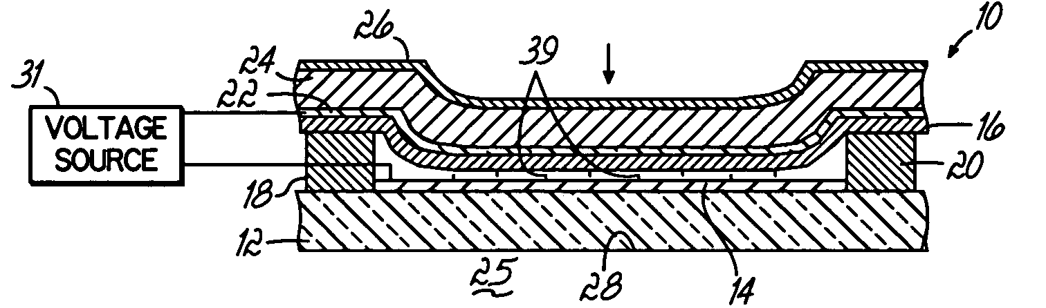
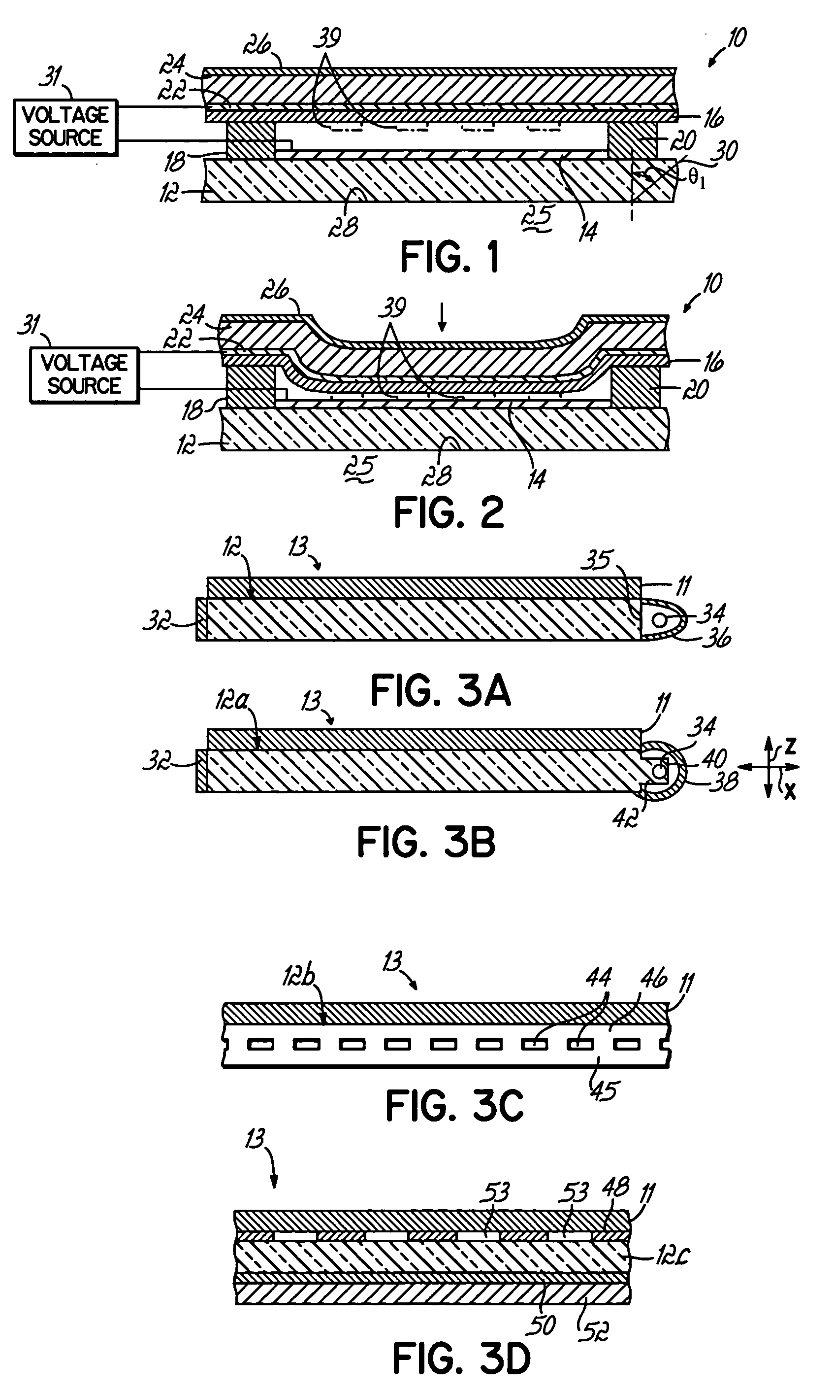
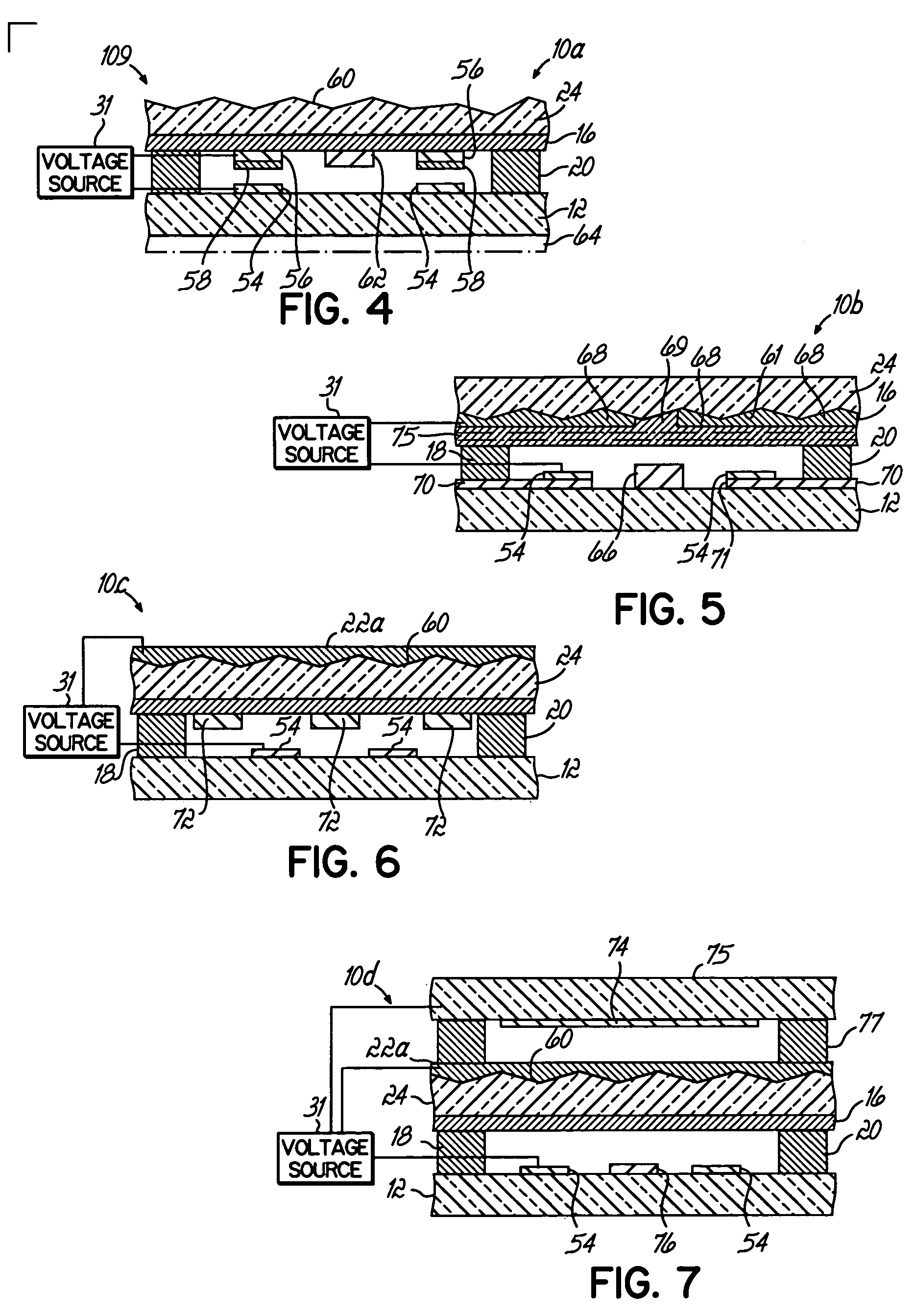
[0105] This photoluminescent resins of Example 2 were screen-printed onto a first acrylic waveguide and baked at 120° C. for 15 minutes to form a hard photoluminescent layer. A second waveguide was then mirrored using an Al adhesive tape and InGaN LEDs attached through apertures in the tape. An silicone oil drop was placed at several regions between the first waveguide and second waveguide, the waveguides then sandwiched together, in order to measure the effective device contrast ratio achievable using electro-static or electrowetting based modulation in an LWC device.

Waveguide Dimensions:about 2″× 4″, about 2 mm thicknessPump Specifications:4 InGaN violet LEDs, 10 mA eachPower requirement:3.5 V, 40 mA, 0.14 WNon CoupledCoupledContrast Ratiored 0.1 cd / m2 50 cd / m2500:1green 0.3 cd / m2105 cd / m2300:1blue0.15 cd / m2 35 cd / m2200:1Waveguide Luminance:violet 0.1 cd / m2 (at imperfections)Appearance:Transparent

[0106] An interesting comparison may be made to prior art. First, for the same opti...


PUM


Abstract

A light emissive display having a specular waveguide that propagates short wavelength light and photoluminescent features adjacent to the waveguide that fluoresce, for example, in visible red, green, blue, and mixed colors when selectively coupled with the short wavelength light. The photoluminescent layers emit light primarily and, therefore, efficiently in the direction of an observer only. This light emissive display may be utilized as a planar light source, as patterned information signage, or as a re-configurable information display containing intensity modulated pixels. The light emissive display may be enhanced optically such that only a small portion of ambient light is reflected from the display while preserving the majority of emitted display luminance.

Description

FIELD OF THE INVENTION [0001] The invention relates to light emissive devices and, more specifically, to light emissive devices having improved efficiency and robustness. BACKGROUND OF THE INVENTION [0002] Many technologies are currently being developed to provide the next generation of flat panel, projection, flexible, and micro-displays. Flat-panel emissive displays, which emit light in a lambertian behavior, are considered by consumers to be the most attractive display. Despite the human eyes natural affinity for emissive displays, liquid crystal displays (LCD) currently dominate the commercial display market. Because LCD's filter white light, which passes through polarizers, a perceptible variance in image quality is observed with view angle. Furthermore, the vast majority (approximately 90 percent or greater) of light in a LCD never reaches the viewer because of unavoidable absorption in thin film polarizers and color filters, and other optical losses in the LCD. Generally, pol...

Claims


Application Information

Patent Timeline
IPC IPC(8): G02B6/35G02B26/02G09F9/37
CPCY10S385/90G02B26/02
Inventor STECKL, ANDREW J.HEIKENFELD, JASON C.
Owner CINCINNATI UNIV OF
Why Eureka
Try Eureka