
Method of driving plasma display panel

a technology of alternating current and display panel, which is applied in the direction of instruments, static indicating devices, etc., can solve the problems of significant influence, deviation in discharge characteristics of discharge spaces distributed over the screen of an ac pdp, and wall voltage over discharge cells, etc., and achieves reduced background luminance, long reset time, and high background luminance.

Active Publication Date: 2006-12-19
SEOUL NAT UNIV R&DB FOUND
View PDF3 Cites 9 Cited by
  • Summary
  • Abstract
  • Description
  • Claims
  • Application Information

AI Technical Summary

Benefits of technology

[0023]Accordingly, the present invention has been made keeping in mind the above problems occurring in the prior art, and an object of the present invention is to provide a method and apparatus for driving an AC PDP, which can overcome disadvantages of conventional reset methods for AC PDPs in which stability is insufficient, background luminance is high and a long reset time is required, so that background luminance is reduced and the time required for a reset period is shortened while the stability and the address margin are sufficiently maintained, thus improving reset performance.
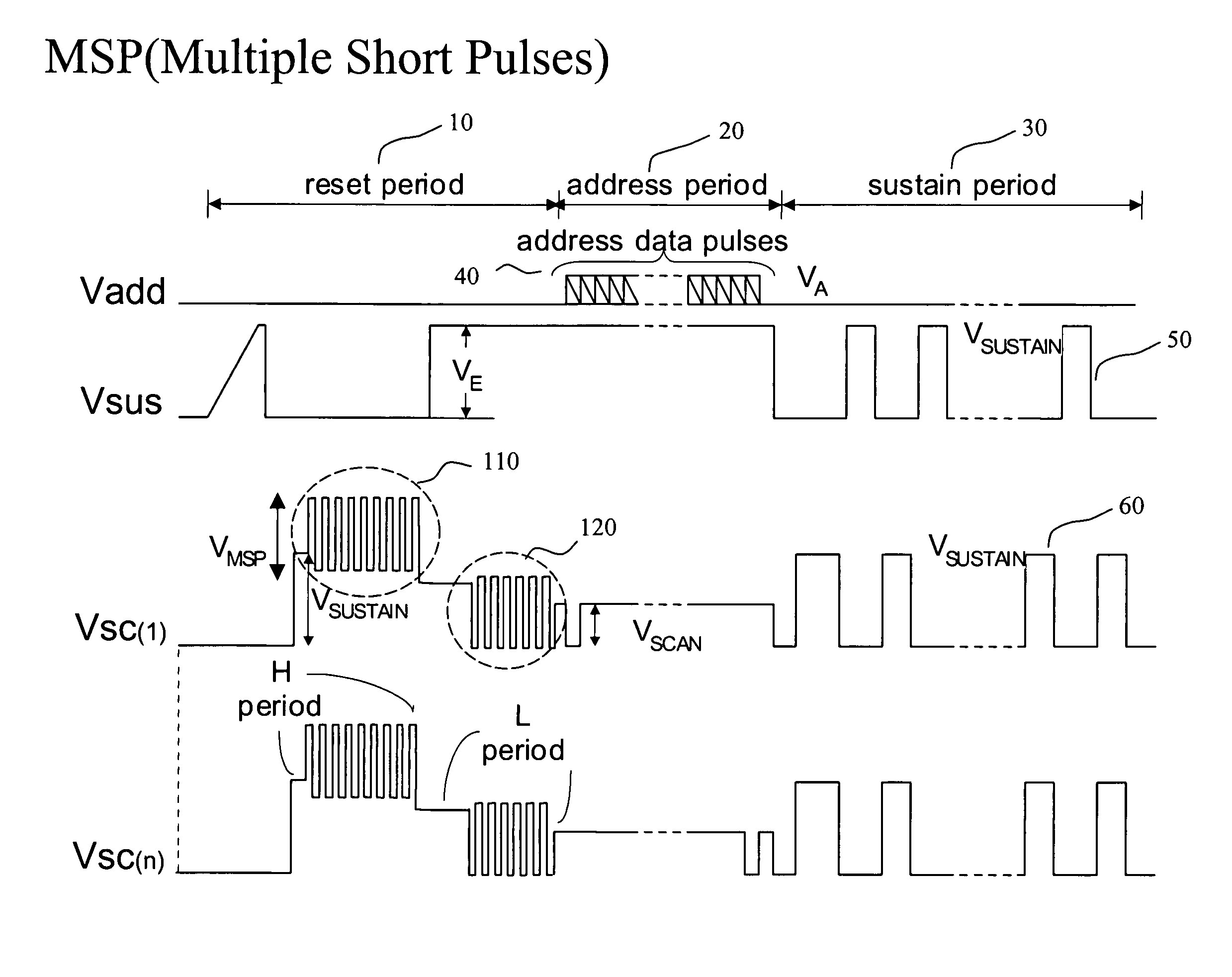
[0024]Another object of the present invention is to provide a method and apparatus for driving an AC PDP, where a reset operation is fulfilled by successively generating short discharges each duration of which is limited, so that each of the discharge is rapidly turned off before discharge current and light emission grow large, that is, in its initial stage, thus reducing the background luminance, shortening the reset time and providing the sufficient stability of driving.

Problems solved by technology

First, the set-up period must function to prime discharge spaces so as to perform reliable driving in selective address and sustain periods thereafter.
Second, the set-up period must uniformly establish a predetermined amount of wall voltage required for a stable operation in a given sub-field. The amount of wall voltage is determined according to a degree required to allow a selective write operation to be normally performed during the address period of each sub-field. A very important point is that a predetermined amount of wall voltage, which must be established during the set-up period of a given sub-field, must not be affected by the amount of wall voltage that remains from the previous sub-field. If predetermined amounts of wall voltages of some discharge cells are affected by the status of the previous sub-field, the distributions of wall voltages over discharge cells become uneven. As a result, the selective write operation or the sustain operation may be erroneously performed.
The discharge characteristics of discharge spaces distributed over the screen of an AC PDP may deviate somewhat, and are significantly affected by circumstances around the discharge spaces.
Accordingly, since in this method, the background luminance level is considerably high, and this method is disadvantageous in that darkroom contrast ratio is low.
It is also known that waveforms with lengthy time constants and low voltage are applied as the two erase pulses, which causes the time required for the reset period to be relatively long.
The remaining time can be assigned to the sustain period by reducing the time required for the reset period, which results in the increase of brightness.

Method used


Image

  • Method of driving plasma display panel
  • Method of driving plasma display panel
  • Method of driving plasma display panel

Examples


Embodiment Construction

[0053]Reference now should be made to the drawings, in which the same reference numerals are used throughout the different drawings to designate the same or similar components.

[0054]FIG. 5 is a driving waveform chart showing a preferred embodiment of the present invention using Multiple Short Pulses (MSP) during the reset period in a single sub-field.

[0055]In the preferred embodiment, a single sub-field consists of a reset period 10, an address period 20 and a sustain period 30. In the reset period 10, a write operation H to all of the discharge cells in the AC PDP is performed by accumulating sufficient wall charges, and an erase operation L is performed for leaving wall charge of a desired level to assure a subsequent data write operation during the address period 20 to be easily performed. While the voltages of the sustain electrodes are maintained at a reference voltage (for example, 0V but it can be higher voltage or even floated to reduce the background light emission during H...


PUM


Abstract

The present invention is to provide a method and apparatus for driving an AC PDP, where background luminance is reduced and the time required for a reset period is shortened while the stability and an address margin are sufficiently maintained, thus improving reset performance. The present invention provides a method of driving an Alternating Current (AC) Plasma Display Panel (PDP) comprising the steps of: applying a drive signal including a plurality of successive short pulses during the reset period; addressing at least a part of the discharge cells by applying data pulses to at least a part of said electrodes to enable selective discharge of said discharge cells according to image data during the address period; wherein, during the reset period, the plurality of short pulses form a plurality of discharges each duration of which is limited; and wherein a standardized wall charge is formed in each of the discharge cells due to the plurality of discharges so that the selective discharge is easily generated by application of data pulses during the address period.

Description

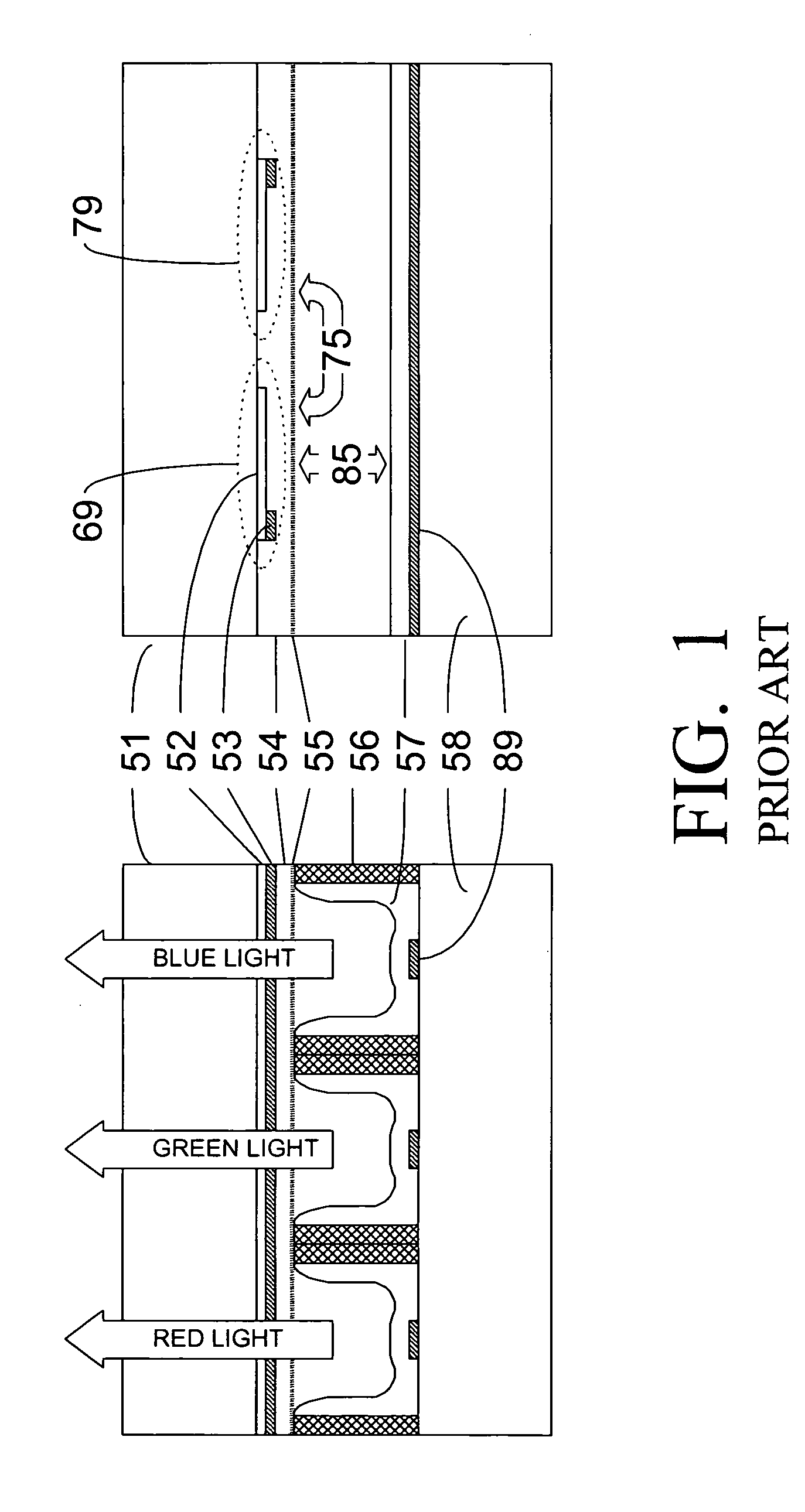
BACKGROUND OF THE INVENTION[0001]1. Field of the Invention[0002]The present invention relates generally to a method and apparatus for driving an alternating current plasma display panel (AC PDP), and, more particularly, to a method and apparatus for driving an alternating current plasma display panel, whereby image contrast is improved by reducing the emission of background light and an uniform and stable wall charge distribution is established over the entire panel though a relatively short reset time is used, thus allowing a subsequent data write operation to be easily performed.[0003]2. Description of the Related Art[0004]Various structures of Alternating Current (AC) Plasma Display Panels (PDPs) exist. Well-known and widely used ones of these structures are somewhat similar. A typical structure of AC PDPs is illustrated in FIG. 1. As illustrated in FIG. 1, an AC PDP includes an upper panel and a lower panel. The upper panel includes a glass substrate 51, a plurality of scan elec...

Claims


Application Information

Patent Timeline
Patent Type & Authority Patents(United States)
IPC IPC(8): G09G3/28G09G3/288
CPCG09G3/2807G09G3/2927G09G3/296G09G2310/066G09G2320/0238
Inventor WHANG, KI-WOONGYANG, JIN-HOJUNG, WOO-JOON
Owner SEOUL NAT UNIV R&DB FOUND
Learn More