
Assembly method of miniature thermal protector

A technology of thermal protector and assembly method, applied in the direction of thermal switch parts, electrical components, electrical switches, etc., can solve the problems of secondary abnormal conduction, small electrical insulation gap, risk, etc., and achieve long reset time, The effect of ensuring consistency and ensuring stability

Active Publication Date: 2019-03-05
HANGZHOU STAR SHUAIER ELECTRIC APPLIANCE
View PDF6 Cites 0 Cited by
  • Summary
  • Abstract
  • Description
  • Claims
  • Application Information

AI Technical Summary

Problems solved by technology

[0003] The above-mentioned patents have the following disadvantages in actual use: 1. Since the electrical insulation gap between the two separated metal first cover parts and the second cover part and the spiral heating wire is small, generally only 0.5-1mm, the heating wire is sealed in the heating wire after welding. Inside the metal cover, its position is guaranteed by the welding process, and the electrical insulation gap is small, so it is difficult to measure accurately. If an instantaneous large current is encountered, the heating wire will expand when it is energized, and the spiral heating wire will be deformed under the thermal effect, such as on the heating wire. The arch may be short-circuited with two separate metal covers, resulting in the failure of the current protection feature. In severe cases, the spiral heating wire will be blown and the thermal protector will be defective, resulting in the motor not working normally; 2. The circular arch structure of the metal cover, Not only is it easy to cause a partial short circuit of the heater and cause the product to fail, but sometimes a secondary abnormal conduction is formed after the short circuit, causing a greater safety risk
The disadvantages are as follows: Since the semi-circular heating wire is fixed in the semi-circular heating wire loading cavity, if an instantaneous large current is encountered, the heating wire will expand when energized, and the spiral heating wire will be deformed under the thermal effect, which is extremely dangerous It may be upturned. At this time, the heating wire will be short-circuited with the bimetal sheet, resulting in the failure of the current protection feature.

Method used


Image

  • Assembly method of miniature thermal protector
  • Assembly method of miniature thermal protector
  • Assembly method of miniature thermal protector

Examples


Embodiment Construction

[0039] The preferred embodiment of the present invention will be described in detail below in conjunction with the accompanying drawings.

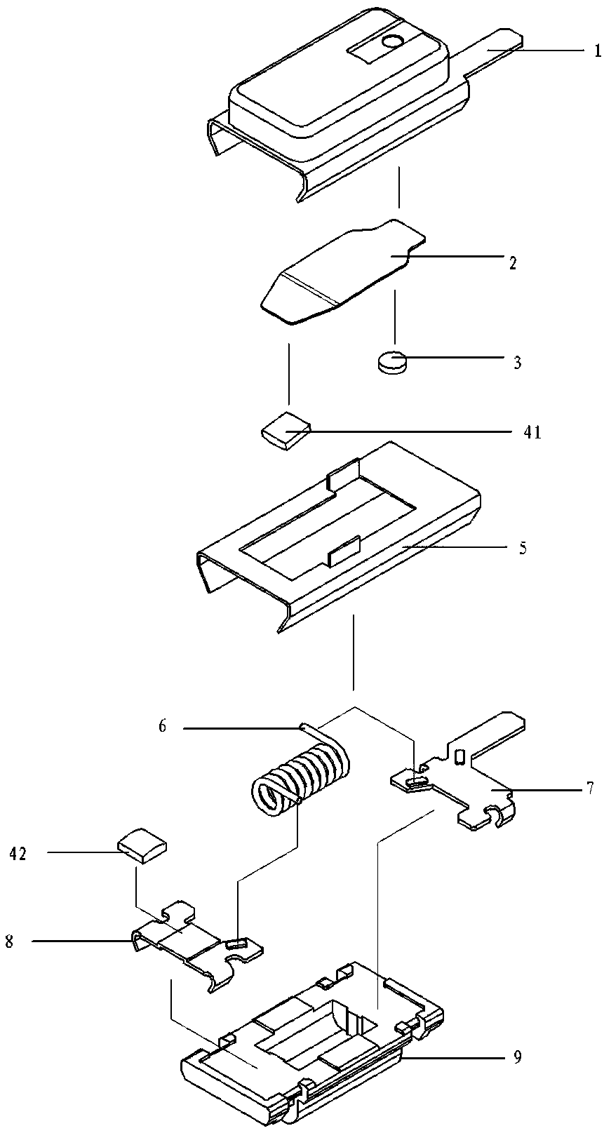
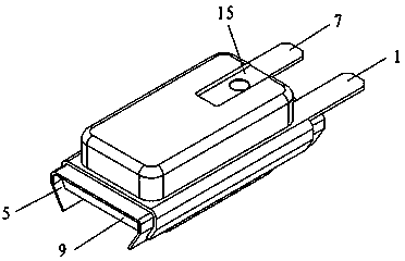
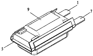
[0040] see Figure 1 to Figure 15 , the miniature thermal protector of the present invention includes a shell 1, a bimetallic sheet 2, a liner 3, a movable contact 41, a static contact 42, an insulator 5, a heating wire 6, an insert 7, a static foot 8, and a non-metallic base 9.

[0041] There is a rectangular boss 14 inside the casing 1, and a circular boss 13 is arranged on the rectangular boss 14. A group of bimetallic strips 2 with a movable contact 41 are reliably connected to the circular boss 13 through the gasket 3, forming a shell assembly 101, and make the effect of welding strength better.

[0042] The casing 1 is provided with a casing output end 11, and the casing 1 is directly connected with two inwardly bent casing corners 1 121 and 2 122, which are fastened to the non-metallic base 9 so as to facilitate the matching conne...


PUM


Abstract

The invention relates to a miniature thermal protector assembly method, which comprises the following steps: welding a bimetal strip and a movable contact to form a weld member 1, welding a housing and a gasket to form a weld member 2, and then, welding the weld member 1 and the weld member 2 to form a housing assembly; welding a static pin and a static contact, and enabling a heating wire to be welded with an insertion slice, and then, to be welded with a static pin assembly to form a heating wire assembly; then, enabling the heating wire assembly to be arranged to an insertion slice cavity, a static pin cavity and a heating wire cavity of a non-metal base correspondingly, and riveted with the non-metallic base to form a base assembly; after finishing assembly of the base assembly, carrying out heating wire power-on shaping process; and finally, arranging an insulation member between the housing assembly and the base assembly, assembly being finished. The method enables the heating wire to be accommodated in the specially-made non-metal base, so that partial short circuit of a heater is not caused, and secondary abnormal conduction does not occur; and the method is safe and reliable to use and can obtain a longer reset time.

Description

technical field [0001] The invention relates to an assembly method of a miniature thermal protector, which is mainly used for simultaneous protection of over-temperature rise and over-current of micro-motors or other control circuit boards. Background technique [0002] Chinese Patent No. ZL200410098345.1 discloses an invention patent named "Low Current Motor Protector". The two ends of the spiral heating wire are connected to two separate metal shells, which are connected by spot welding, and the metal bottom plate and the two separate metal shells are separated by high-temperature insulating parts. The above-mentioned parts are connected After that, the power circuit of the thermal protector is formed; specifically, the patent features include: the metal shell and the flange on it, the first cover part and the second cover part separated on the metal cover, the first cover part and the second cover part At least one of the cover parts forms a circular arch structure, a he...

Claims


Application Information

Patent Timeline
Patent Type & Authority Patents(China)
IPC IPC(8): H01H11/00H01H37/52H01H37/70
CPCH01H11/00H01H37/52H01H37/70
Inventor 孙海孙华民徐宇军陈晓强
Owner HANGZHOU STAR SHUAIER ELECTRIC APPLIANCE
Learn More