Method of displaying an image on a screen of an aircraft

a technology of aircraft and image, applied in the field of displaying an image on an aircraft screen, can solve the problems of not being able to achieve the effect of ensuring flight integrity, not being able to ensure, and being much less effective with characters, and achieve good contrast

Active Publication Date: 2011-01-27
AIRBUS OPERATIONS (SAS) +1
View PDF7 Cites 3 Cited by
  • Summary
  • Abstract
  • Description
  • Claims
  • Application Information

AI Technical Summary

Benefits of technology

Advantageously, the screen is a matrix screen.
The invention also provides a device for controlling the display of an image on a screen in an aircraft cockpit, the device being suitable for:controlling a first display on the screen of an image comprising a background; and thencontrolling a second display so that, in at least one zone of the image that is determined independently of the background, the background presents a non-zero second mean luminance that is less than a first mean luminance that it presented during the first display.
Preferably, the device comprises at least one graphic memory having the following graphics layers:a layer forming the background of the image;an intermediate layer suitable for attenuating the mean luminance of the background at least in the zone; anda layer forming at least one sign.
The invention also provides a method of displaying an image on a screen of a cockpit of an aircraft, wherein the control means control the display on the screen of an image comprising a background in such a manner, that at least in a zone of the image that is determined independently of the background, the background presents non-zero mean luminance that is less than mean luminance of the remainder of the background.
Thus, whereas in the first aspect of the invention, the luminance of at least one point is varied in time by comparing two steps of displaying the image or two representations of the image, here the distinction is made in space by distinguishing one zone of the background from the remainder of the background. Once more, good contrast is obtained between the sign and the background visible behind it in the zone in a manner that is simple.

Problems solved by technology

Nevertheless, it does not constitute primary means for guaranteeing flight integrity.
Nevertheless, that does not suffice to ensure that the symbology is clearly legible under all circumstances, in particular if the background is moving or cluttered with numerous graphics elements of different colors.
It is found to be much less effective with characters, or thin traces that are displayed on a background presenting high resolution.

Method used


Image

  • Method of displaying an image on a screen of an aircraft
  • Method of displaying an image on a screen of an aircraft
  • Method of displaying an image on a screen of an aircraft

Examples


Embodiment Construction

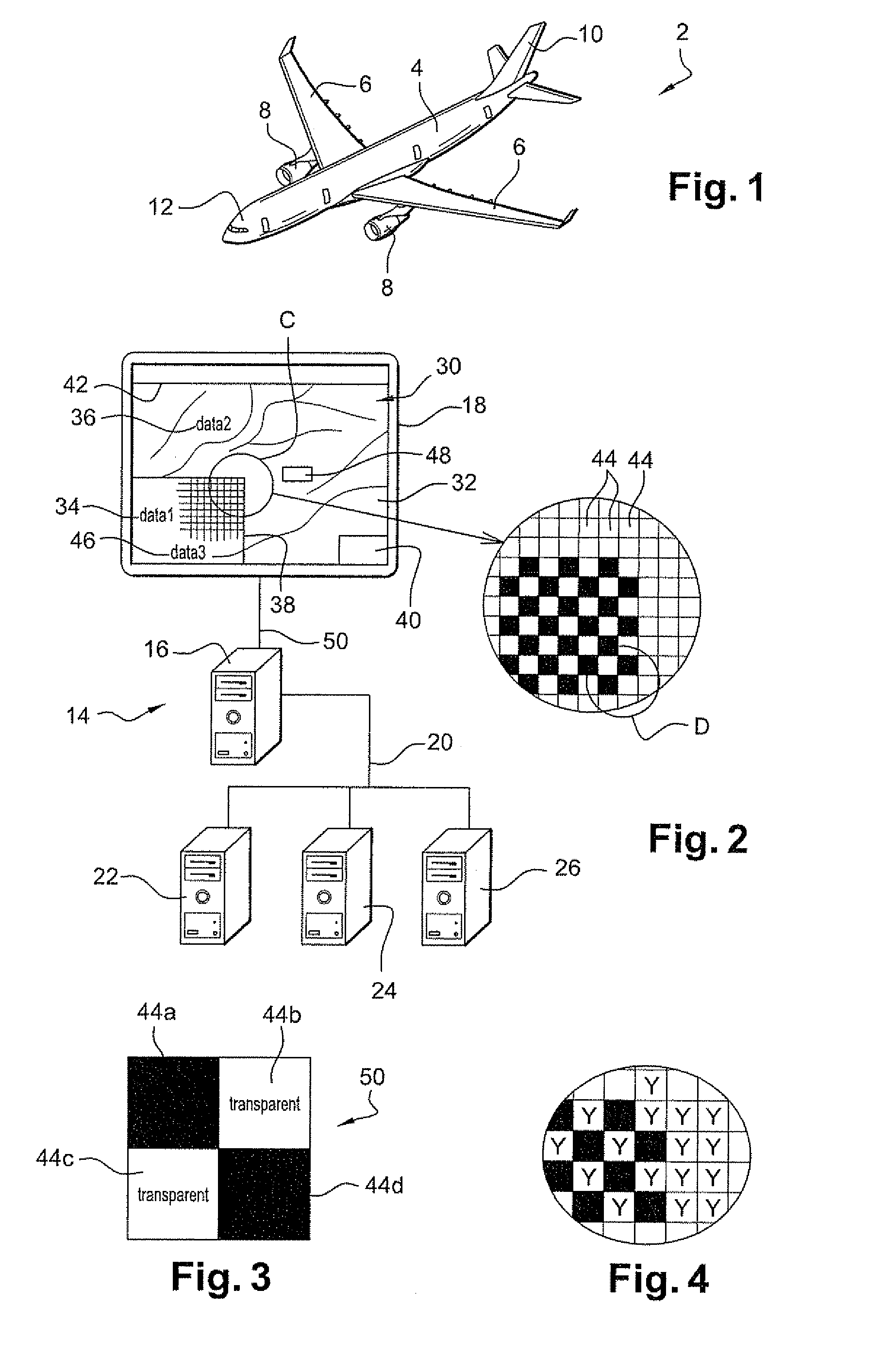
FIG. 1 shows an aircraft 2 having the method of the invention implemented on board. The aircraft shown is specifically an aerodyne, here an airplane comprising a fuselage 4, two wings 6, two engines 8 carried by respective ones of the wings, and a tail 10. At the front of the fuselage, the airplane has a cockpit 12 occupied by one or more pilots.

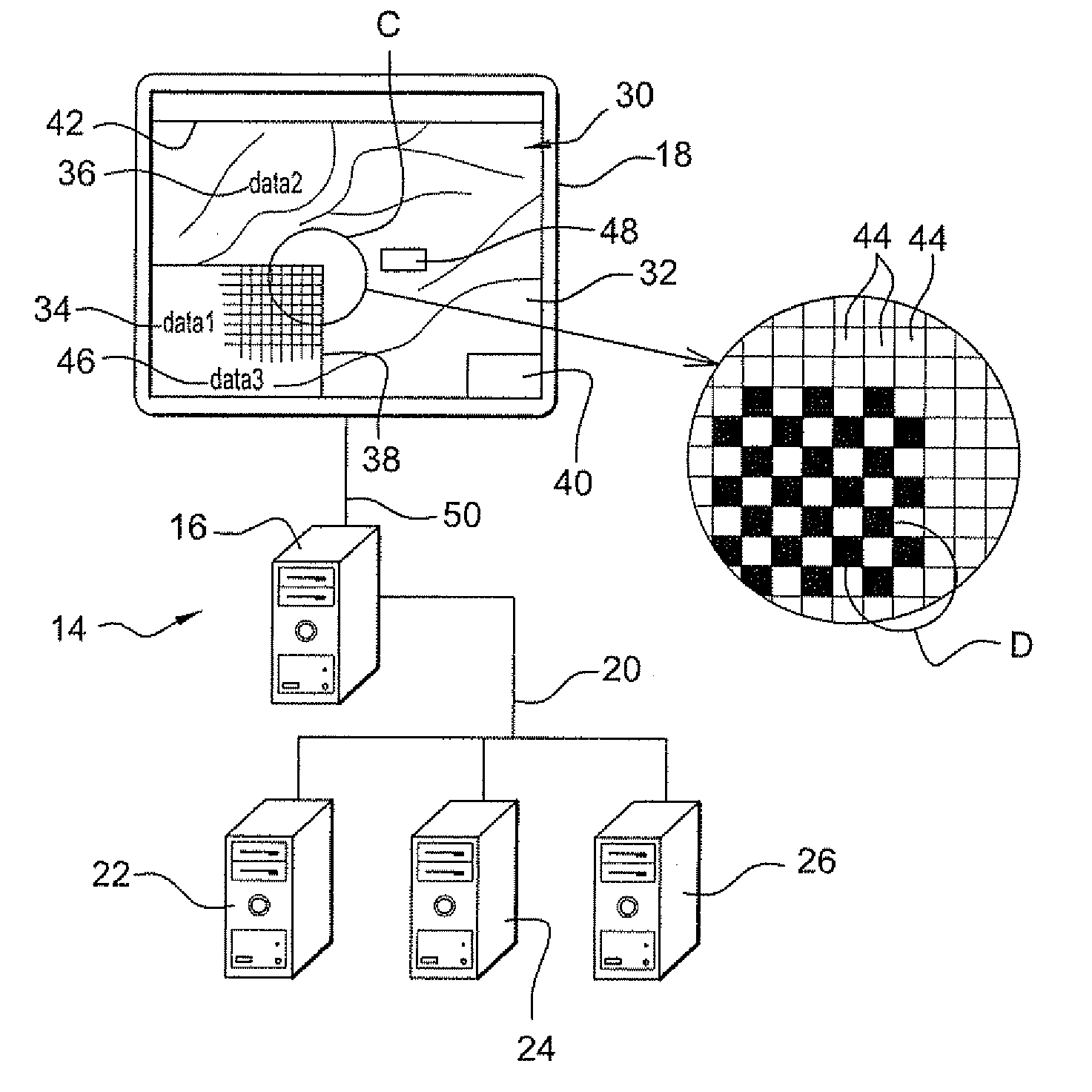
The cockpit includes one or more (visual) display systems. The description below relates to one such display system 14. The system comprises a computer 16 and a screen 18 connected to the computer. Specifically the screen is a matrix screen, e.g. a liquid crystal screen. Unlike the screen 18, it is entirely possible for the computer 16 to be located outside the cockpit.

The system 14 is connected by on-board telecommunications means 20 to other on-board systems 22, 24, and 26, each including at least one computer. These systems 22 to 26 may relate to functions as varied as mapping, radar imaging, a terrain database, satellite imaging, the fli...


PUM


Abstract

In one aspect of the method for displaying an image on a screen of a cockpit of an aircraft, control means:
    • control a first display on the screen of an image comprising a background; and then
    • control a second display so that, in at least one zone of the image that is determined independently of the background, the background presents a non-zero second mean luminance that is less than a first mean luminance that it presented during the first display.
In another aspect, the control means control the display on the screen of an image comprising a background in such a manner, that at least in a zone of the image that is determined independently of the background, the background presents non-zero mean luminance that is less than mean luminance of the remainder of the background.

Description

The invention relates to aircraft, and in particular to displaying images and data on a screen of an aircraft cockpit.BACKGROUND OF THE INVENTIONIt is known to provide multifunction liquid crystal screens in the visual display systems of aircraft cockpits, where such screens are capable of displaying a large amount of information simultaneously. The information may have a variety of presentations:text and simple crosshairs generated by the display unit;a bitmap type colored background provided by a system external to the visual display system; anda complex video image also provided by an external system.In order to optimize graphics processing and to guarantee correct priority levels for the symbology generated by the visual display system, it is known that the graphics memory that defines the content of the digital image for display on the matrix of the screen may be organized as a plurality of graphics planes, specifically:a symbology plane;a matrix or bitmap plane; anda video pla...

Claims


Application Information

Patent Timeline
Patent Type & Authority Applications(United States)
IPC IPC(8): G01C23/00
CPCG06F3/147G09G5/10G09G2380/12G09G2340/10G09G2340/125G09G5/30
Inventor GEORGES, LAURENTCABARET DE ALBERTI, REMILAMBINET, LAETITIABRUNET, LAURENT
Owner AIRBUS OPERATIONS (SAS)
Why Eureka
Try Eureka