Eye Imaging

a technology for imaging eyes and eyes, applied in the field of eye imaging, can solve the problems of difficulty in performing an accurate examination, affecting the accuracy of examination, and the use of slit lamps is typically uncomfortable for patients with specific eye diseases

Pending Publication Date: 2021-03-04
KONAN MEDICAL USA
View PDF3 Cites 0 Cited by
  • Summary
  • Abstract
  • Description
  • Claims
  • Application Information

AI Technical Summary

Benefits of technology

[0011]An embodiment of the system also can include one or more ambient sensors, which can acquire data regarding the ambient environment of the illumination device(s) and / or the imaging device(s). For example, the system can include at least one ambient light sensor, which can acquire data corresponding to an amount of ambient light present at one or more locations near the eye of the patient being illuminated and imaged or the room from which general lighting may provide extraneous ambient light to the patient's eye(s). The control system can process the data to determine a background luminance present. The control system can provide feedback to the user regarding the background luminance, such as indicating that the background luminance should be reduced, providing a level of the background luminance, and / or the like. Such feedback can be used to provide a consistency in examination imaging from time to time and subject to subject. The control system can account for the background luminance when evaluating the image data (e.g., calculating an average background luminance for the region(s) without any particles).

Problems solved by technology

Such examiner determinations are subject to various sources of error including: individual bias of visualized material; a dynamically moving field of cells; no precision controls on volume or other scene variables; etc.
Moreover, use of the slit lamp is typically uncomfortable for patients with specific eye diseases.
In this case, the photophobic patient experiences significant discomfort while being exposed to the bright light required for the examiner to visualize microscopic cellular detail, rendering further difficulty in performing an accurate examination, e.g., due to uncontrolled eye and / or head movement by the patient, reflexive, uncontrolled blinking, etc.

Method used


Image

  • Eye Imaging
  • Eye Imaging
  • Eye Imaging

Examples


Embodiment Construction

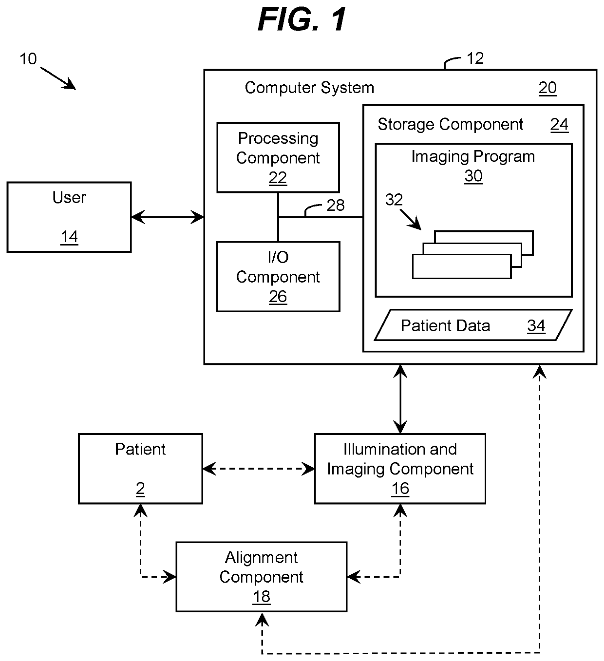
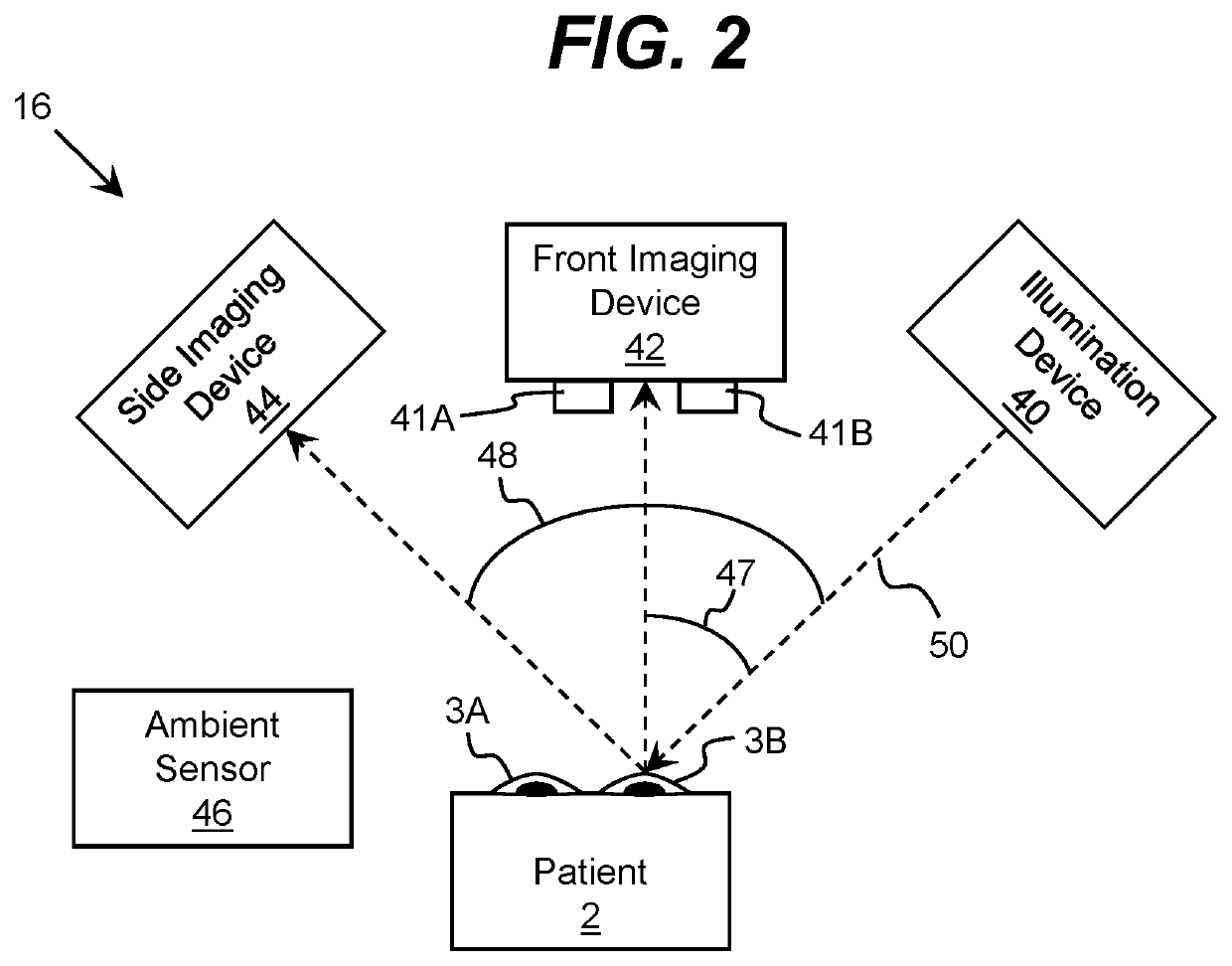
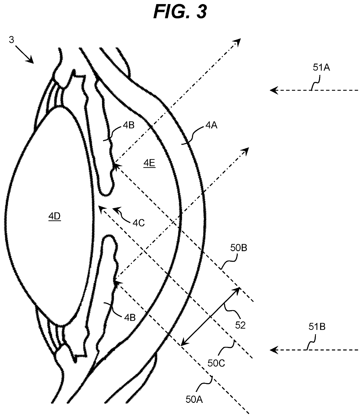
[0019]As indicated above, aspects of the invention provide a solution for imaging an eye and evaluating the eye using the image data. An embodiment of the invention provides a system comprising an illumination device configured to illuminate a linear volume of aqueous fluid of an eye of a patient. The illumination device can be located in a range between 25 to 65 degrees from a line of sight of the eye. The illumination device can project a beam of light, the dimensions of which can be mechanically and / or digitally constrained. The system can further comprise at least one imaging device configured to acquire image data of the eye, e.g., while being illuminated by the illumination device. The aqueous fluid can be located behind a portion of the cornea located in front of the iris, e.g., the anterior chamber of the eye.

[0020]The image data can be evaluated to determine one or more attributes of the eye, such as at least one of: a presence of an inflammatory process in the aqueous flui...


PUM


Abstract

A solution for imaging an eye of a patient is described. An illumination device can illuminate a linear volume of aqueous fluid of the eye of the patient with visible and / or infrared light from a location in a range between 25 to 65 degrees from a line of sight of the eye. At least one imaging device can acquire image data of the eye while it is being illuminated by the illumination device. The image data can be evaluated to determine one or more attributes of an aqueous fluid in an anterior segment of the eye delimited by the posterior surface of the cornea and the most anterior surfaces of the iris or lens and / or one or more attributes of the iris, eye, or surrounding tissues.

Description

REFERENCE TO RELATED APPLICATIONS[0001]The current application is a continuation-in-part of International Application No. PCT / US2019 / 068855, filed on 28 Dec. 2019, which claims the benefit of U.S. Provisional Application No. 62 / 785,729, filed on 28 Dec. 2018, each of which is hereby incorporated by reference.TECHNICAL FIELD[0002]The disclosure relates generally to imaging an eye, and more particularly, to imaging an eye to evaluate a patient.BACKGROUND ART[0003]One or both eyes of an individual are commonly subjectively evaluated under visible light by an examiner, such as a medical practitioner. Alternatively, the examiner may capture images of the eye(s) to be evaluated by the examiner or alternate medical practitioner to determine one or more of: the presence, progression, severity, and / or the like, of a condition, such as a disease or disorder.[0004]An illustrative condition is iritis or anterior uveitis, which is the inflammation of the iris and / or ciliary body. As part of an e...

Claims


Application Information

Patent Timeline
Patent Type & Authority Applications(United States)
IPC IPC(8): A61B3/00A61B3/14G06V10/25
CPCA61B3/0008A61B3/14A61B3/117G06V40/19G06V40/63G06V10/25G06V2201/03
Inventor STEWART, CHARLES WM.
Owner KONAN MEDICAL USA
Why Eureka
Try Eureka