
Method for driving a gas electric discharge device

a gas electric discharge and discharge device technology, applied in the direction of instruments, static indicating devices, etc., can solve the problems of difficult control of the discharge for addressing, the voltage applied in the addressing must be set, and the strong discharge produces an excessive amount of wall charge in all cells, so as to improve the reliability of driving, reduce the luminance of the background, and improve the effect of contras

Inactive Publication Date: 2006-01-03
MAXELL HLDG LTD
View PDF31 Cites 14 Cited by
  • Summary
  • Abstract
  • Description
  • Claims
  • Application Information

AI Technical Summary

Benefits of technology

[0017]In view of the above described circumstances, an object of the present invention is to solve the problem of the reduction in the voltage margin due to the variations in the firing voltage Vf for improving the reliability of driving. Another object is to reduce the luminance of the background for improving the contrast. Still another object is to relieve limitations on the polarity of applied voltage for increasing flexibility of drive sequences.

Problems solved by technology

For it is difficult to control a discharge for addressing if cells retaining wall charge for sustaining illumination co-exist with cells not retaining the wall charge.
The strong discharge produces an excessive amount of wall charge in all cells.
One problem of the conventional driving method is that, since the wall charge is erased in the address preparation, the voltage applied in the addressing must be set in consideration of variations in the firing voltage Vf of the cells due to subtle differences in the structure of the cells.
Another problem is an increase in the luminance of background.
For this requirement, the number of discharges in each sub-field must be set at least on a two-time basis, and thus delicate adjustment of luminance is impossible.
It is noted that, if the polarity of the sustain voltage Vs in some sub-fields is set different from that in other sub-fields, the voltage for generating the self-erase discharge must be set impractically high.

Method used


Image

  • Method for driving a gas electric discharge device
  • Method for driving a gas electric discharge device
  • Method for driving a gas electric discharge device

Examples


first embodiment

[0074]FIG. 7 shows voltage waveforms illustrating a drive sequence in accordance with the invention. In this figure, the signs X and Y representing the main electrodes are accompanied by numerals (1, 2, . . . , n) indicating the order of lines corresponding to the main electrodes, and the signs A representing the address electrodes are accompanied by numerals (1 to m) indicating the order of columns corresponding to the address electrodes. Like numerals are seen in other figures described later.

[0075]The outline of a drive sequence repeated in every sub-field is as follows:

[0076]In the address preparation period TR, a pulse Pra1 and a pulse Pra2 of different polarities are sequentially applied to all the address electrodes A1 to Am, a pulse Prx1 and a pulse Prx2 of different polarities are sequentially applied to all the first main electrodes X1 to Xn, and a pulse Pry1 and a pulse Pry2 of different polarities are sequentially applied to all the second main electrodes Y1 to Yn. Here ...

second embodiment

[0093]FIG. 9 shows voltage waveforms illustrating a drive sequence in accordance with the invention. From comparison of this embodiment with the embodiment of FIG. 7, it is understood that there is no restriction on the number of the sustain pulses Ps. In the above-discussed embodiment of FIG. 7, the last sustain pulse Ps is applied to the main electrodes X1 to Xn. In this embodiment, on the other hand, the last sustain pulse Ps is applied to the main electrodes Y1 to Yn. This means that the polarities of the wall voltages at the end of the sustain period TS are reverse to those in the embodiment of FIG. 7. However, pulses Prx1, Pry1, Pra1, Prx2, Pry2 and Pra2 of the same conditions as those in the embodiment of FIG. 7 are applied in the address preparation period TR.

[0094]FIG. 10 shows waveforms of the applied voltages and wall voltages in the drive sequence shown in FIG. 9.

[0095]The change of wall voltages in a cell not illuminated in the last sub-field is the same as in FIG. 7. I...

fourth embodiment

[0103]FIG. 12 shows voltage waveforms illustrating a drive sequence in accordance with the invention.

[0104]In the address preparation period TR, a pulse Pry1′ in a rectangular waveform is applied to all the main electrodes Y1 to Yn to produce a predetermined wall voltage in all the cells, prior to the charge adjustment by the application of the pulses Prx2, Pry2 and Pra2. The wave height of the pulse Pry1′ is set to exceed the firing voltages VfXY and VfAY.

[0105]FIG. 13 shows waveforms of the applied voltages and wall voltages in the drive sequence shown in FIG. 12.

[0106]In a cell not illuminated in the last sub-field, one discharge is generated by the application of the pulse Pry1′. This discharge produces the wall voltages VwprXY and VwprAY. The change of the wall voltages after the application of the pulses Prx2, Pry2 and Pra2 is the same as in the first embodiment. However, in the case of the erase addressing, the wave height of the pulse Pry1′ must be set such that the wall vol...


PUM


Abstract

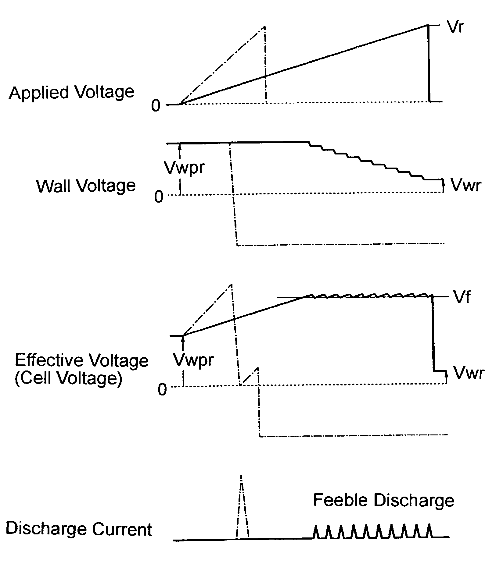
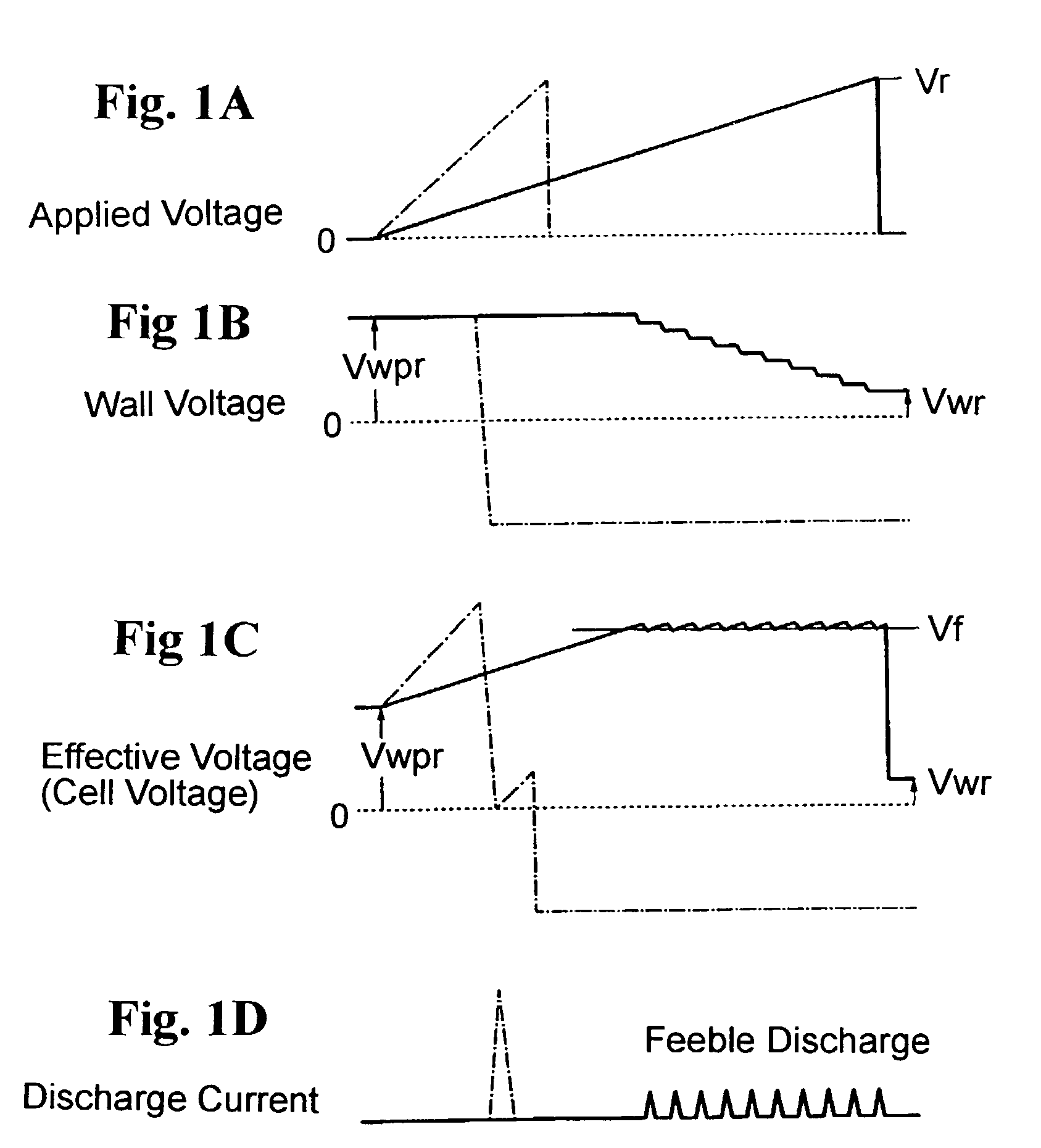
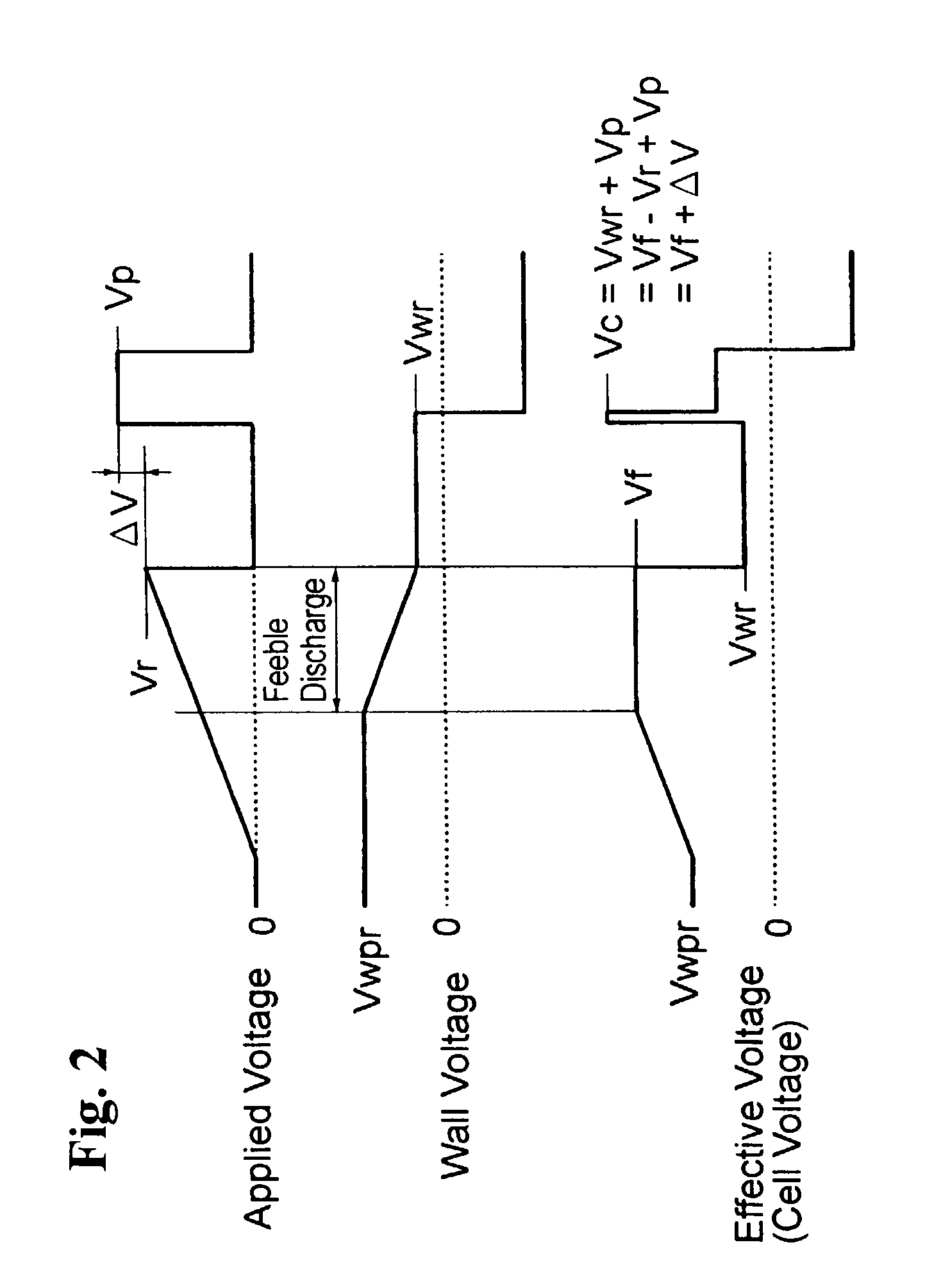
A method for driving a gas electric discharge device which has a first electrode and a second electrode and is constructed such that a wall voltage is capable of being produced between the first and second electrodes. The method includes applying a voltage monotonously rising from a first set value to a second set value, between the first and second electrodes, thereby to generate a plurality of gas electric discharges so as to decrease the wall voltage for charge adjustment during the voltage rise.

Description

CROSS-REFERENCE TO RELATED APPLICATION[0001]This application is a continuation of application Ser. No. 09 / 227,082, filed Jan. 5, 1999, now U.S. Pat. No. 6,456,263. This application is related to Japanese application No. HEI 10(1998)-157107, filed on Jun. 5, 1998, whose priority is claimed under 35 USC §119, the disclosure of which is incorporated by reference in its entirety.BACKGROUND OF THE INVENTION[0002]1. Field of the Invention[0003]The present invention relates to a method for driving gas electric discharge devices typified by PDPs (plasma display panels) and PALC (plasma addressed liquid crystal) display panels.[0004]PDPs have been becoming widespread as large-screen display devices for television since color display became operational with the PDPs. The larger screen a PDP has, the more difficult it is to establish a uniform structure in all cells on the screen, and therefore, the PDP is required to be driven by a driving method which has a large voltage margin of voltage to...

Claims


Application Information

Patent Timeline
Patent Type & Authority Patents(United States)
IPC IPC(8): G09G3/28G09G3/288G09G3/20G09G3/291G09G3/292G09G3/298
CPCG09G3/2927G09G3/293G09G3/294G09G3/298G09G3/2022G09G3/2096G09G2360/18G09G3/3662G09G2310/06G09G2310/066G09G2320/0228G09G2320/0238G09G3/296
Inventor HASHIMOTO, YASUNOBUYONEDA, YASUSHIAWAMOTO, KENJIIWASA, SEIICHI
Owner MAXELL HLDG LTD
Learn More