Method of driving gate lines, gate line drive circuit for performing the method and display device having the gate line drive circuit

a technology of gate line and gate drive circuit, which is applied in the field of display devices, can solve the problems of not effectively controlling the noise signal generated, and achieve the effect of improving driving reliability and enhancing display quality

Active Publication Date: 2010-08-19
SAMSUNG DISPLAY CO LTD
View PDF2 Cites 16 Cited by
  • Summary
  • Abstract
  • Description
  • Claims
  • Application Information

AI Technical Summary

Benefits of technology

[0008]In accordance with an exemplary embodiment of the present invention a method of driving gate lines for improving driving reliability and enhancing display quality is provided.
[0013]In an exemplary embodiment of the present invention, the method of driving gate lines may further include maintaining the voltage of the first node at a low level in response to the first clock signal after the first node is discharged, providing a signal substantially the same as the first clock signal to a second node during a period in which the voltage of the first node is maintained at the low level, and maintaining the gate-off voltage of the output terminal when a signal of the second node or a second clock signal is in a high level.

Problems solved by technology

However, the ASG structures proposed thus far have not effectively controlled the noise signal generated when the temperature of a gate drive part becomes high due to being driven for a long time.

Method used


Image

  • Method of driving gate lines, gate line drive circuit for performing the method and display device having the gate line drive circuit
  • Method of driving gate lines, gate line drive circuit for performing the method and display device having the gate line drive circuit
  • Method of driving gate lines, gate line drive circuit for performing the method and display device having the gate line drive circuit

Examples


Embodiment Construction

[0039]The present invention is described more fully hereinafter with reference to the accompanying drawings, in which exemplary embodiments of the present invention are shown. The present invention may, however, be embodied in many different forms and should not be construed as limited to the exemplary embodiments set forth herein. In the drawings, the sizes and relative sizes of layers and regions may be exaggerated for clarity.

[0040]It will be understood that when an element or layer is referred to as being “on,”“connected to” or “coupled to” another element or layer, it can be directly on, connected or coupled to the other element or layer or intervening elements or layers may be present.

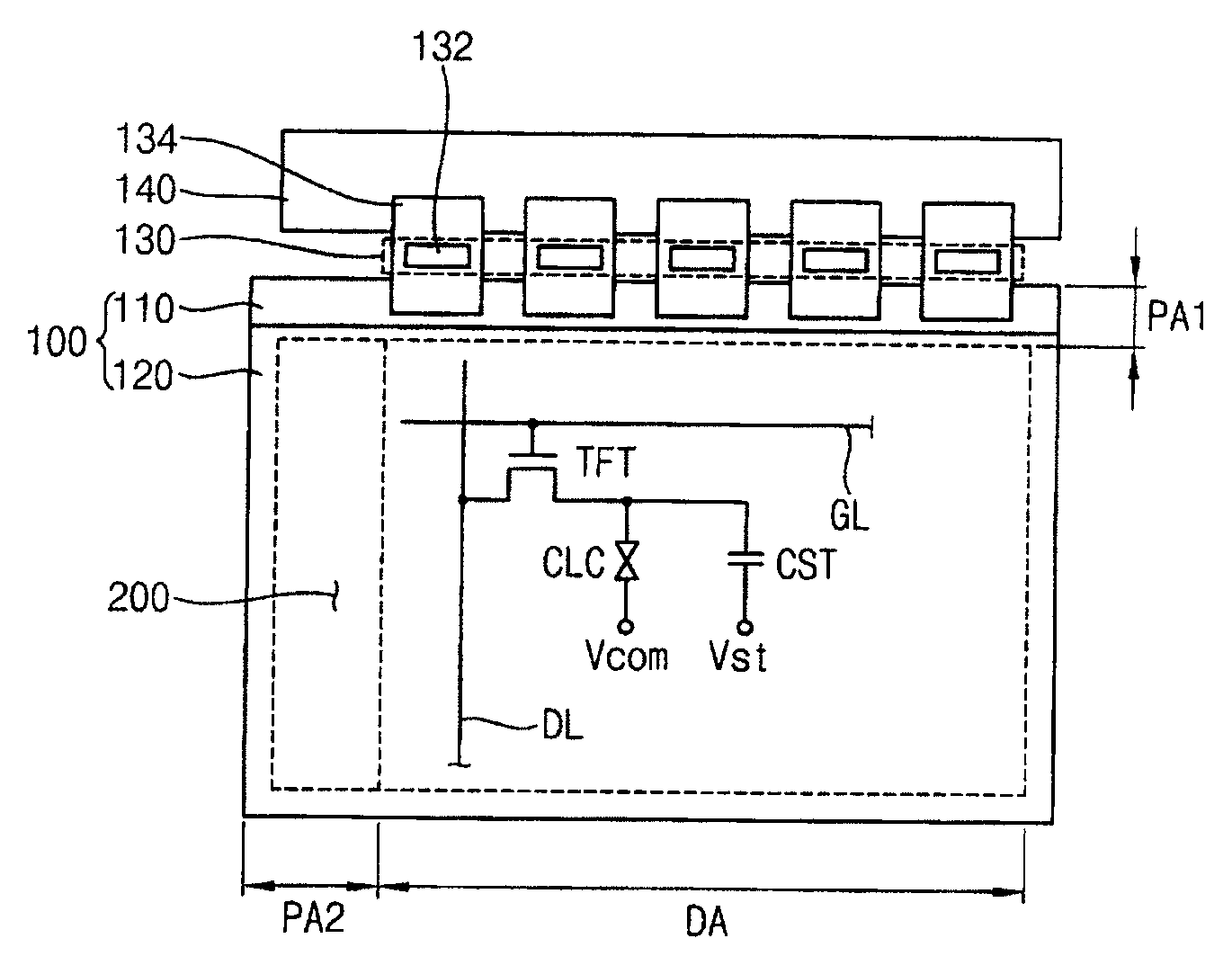
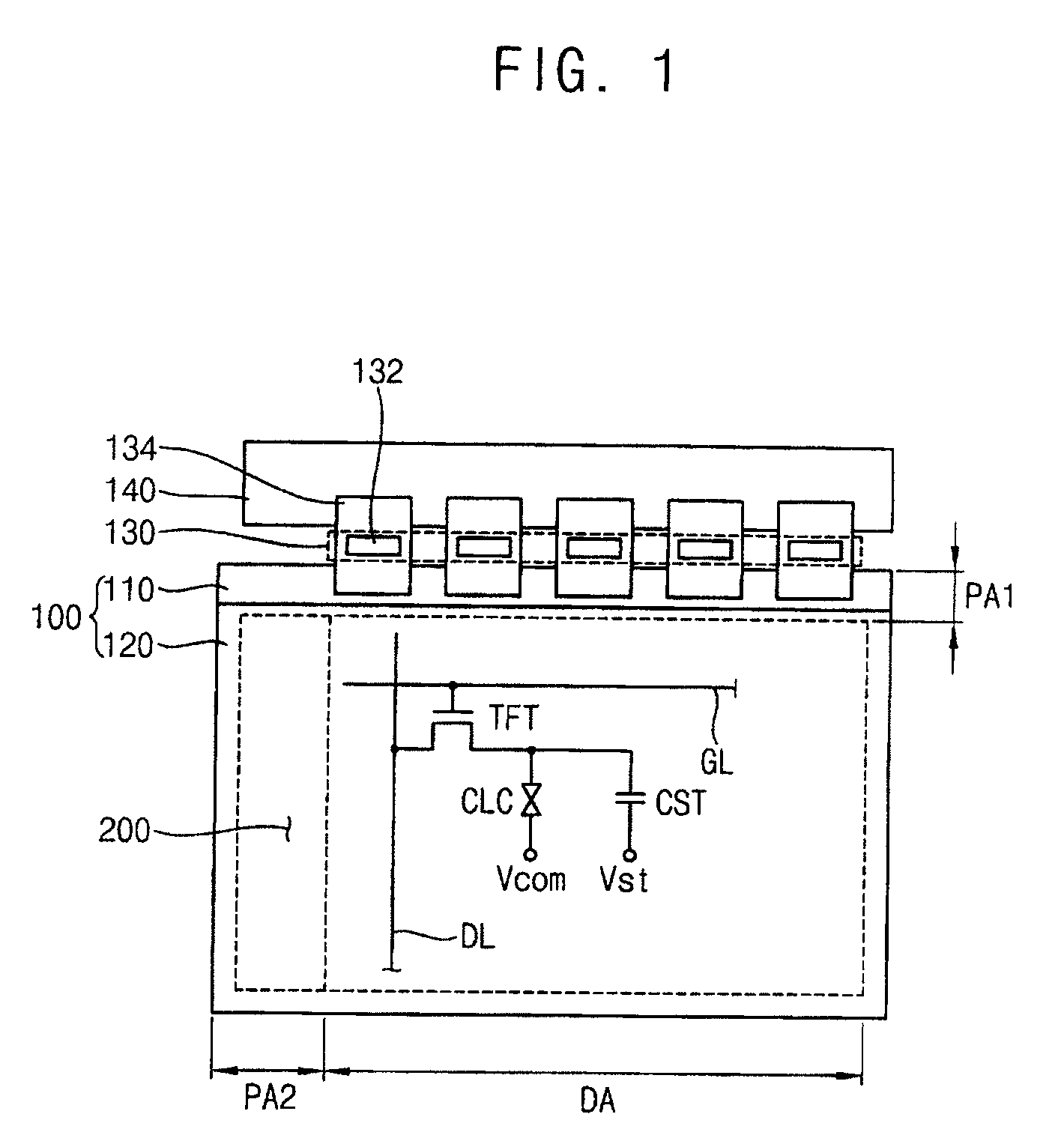
[0041]FIG. 1 is a plan view illustrating a display device according to an exemplary embodiment of the present invention. The display device includes a display panel 100, a gate line drive circuit 200 for driving the display panel 100, and a data line drive part 130 for driving the display panel 1...


PUM


Abstract

A method of driving gate lines is used to activate the gate lines by outputting output signals of stages to the gate lines. A first node is boosted up based upon a carry signal or the vertical start signal from a previous stage. A gate signal that is pulled up is outputted through an output terminal of a present stage based upon a first clock signal which is boosted up. An off-voltage is outputted through the output terminal of the present stage in response to an output signal from a next stage or the vertical start signal. The first node is discharged in response to the output signal from the next stage or a carry signal from a last stage. A positive ripple voltage at the first node is removed by providing a negative ripple voltage to the first node.

Description

CROSS-REFERENCE TO RELATED APPLICATION[0001]This application claims priority to and the benefit of Korean Patent Application No. 2009-12800, filed on Feb. 17, 2009 in the Korean Intellectual Property Office (KIPO), the entire contents of which are incorporated by reference herein.BACKGROUND OF THE INVENTION[0002]1. Field of the Invention[0003]The present disclosure relates to display devices, and, more particularly, to a method of driving gate lines, a gate line drive circuit for performing the method, and a display device having the gate line drive circuit.[0004]2. Discussion of the Related Art[0005]Recently, to reduce manufacturing costs and the total size of a panel module for a display device, an amorphous silicon gate (ASG) technology has been applied that includes simultaneously forming a gate drive circuit in a peripheral area of a panel and a switching device in a display area of the panel.[0006]Since the ASG technology includes selectively outputting a clock signal in which...

Claims


Application Information

Patent Timeline
Patent Type & Authority Applications(United States)
IPC IPC(8): H03B1/00G09G5/00
CPCG09G3/3674G09G2310/0267G11C19/184G11C8/08G09G2310/0286G09G3/36G02F1/133G11C19/00H03K19/00
Inventor KWON, YEONG-KEUNJEON, SANG-JINKIM, YOON-JANGYIM, BAE-HEUKKOO, BON-YONG
Owner SAMSUNG DISPLAY CO LTD
Why Eureka
Try Eureka