Liquid crystal display

a liquid crystal display and liquid crystal technology, applied in non-linear optics, instruments, optics, etc., can solve the problems of black brightening phenomenon that is quite uncomfortable for viewers, reduce contrast ratio, and black cannot be clearly displayed, so as to improve black representation performance, reduce contrast ratio, and increase luminance of black

Active Publication Date: 2005-06-30
PANASONIC LIQUID CRYSTAL DISPLAY CO LTD +1
View PDF2 Cites 112 Cited by
  • Summary
  • Abstract
  • Description
  • Claims
  • Application Information

AI Technical Summary

Benefits of technology

[0038] Polarized light incident to the liquid crystal display panel is partially deporalized when the light passes through the panel and unnecessary leakage light is emitted. This consequently increases luminance of black to reduce the contrast ratio. By disposing a component to selectively absorb the characteristic leakage light at black representation, there is provided a liquid crystal display in which performance of black representation is improved and a high contrast ratio is obtained.

Problems solved by technology

Particularly, to view screen images of a large-screen television set in a dark room such as a home theater, a black brightening phenomenon is quite uncomfortable for the viewers.
Therefore, the contrast ratio reduces and black cannot be clearly displayed.

Method used


Image

  • Liquid crystal display
  • Liquid crystal display
  • Liquid crystal display

Examples


first embodiment

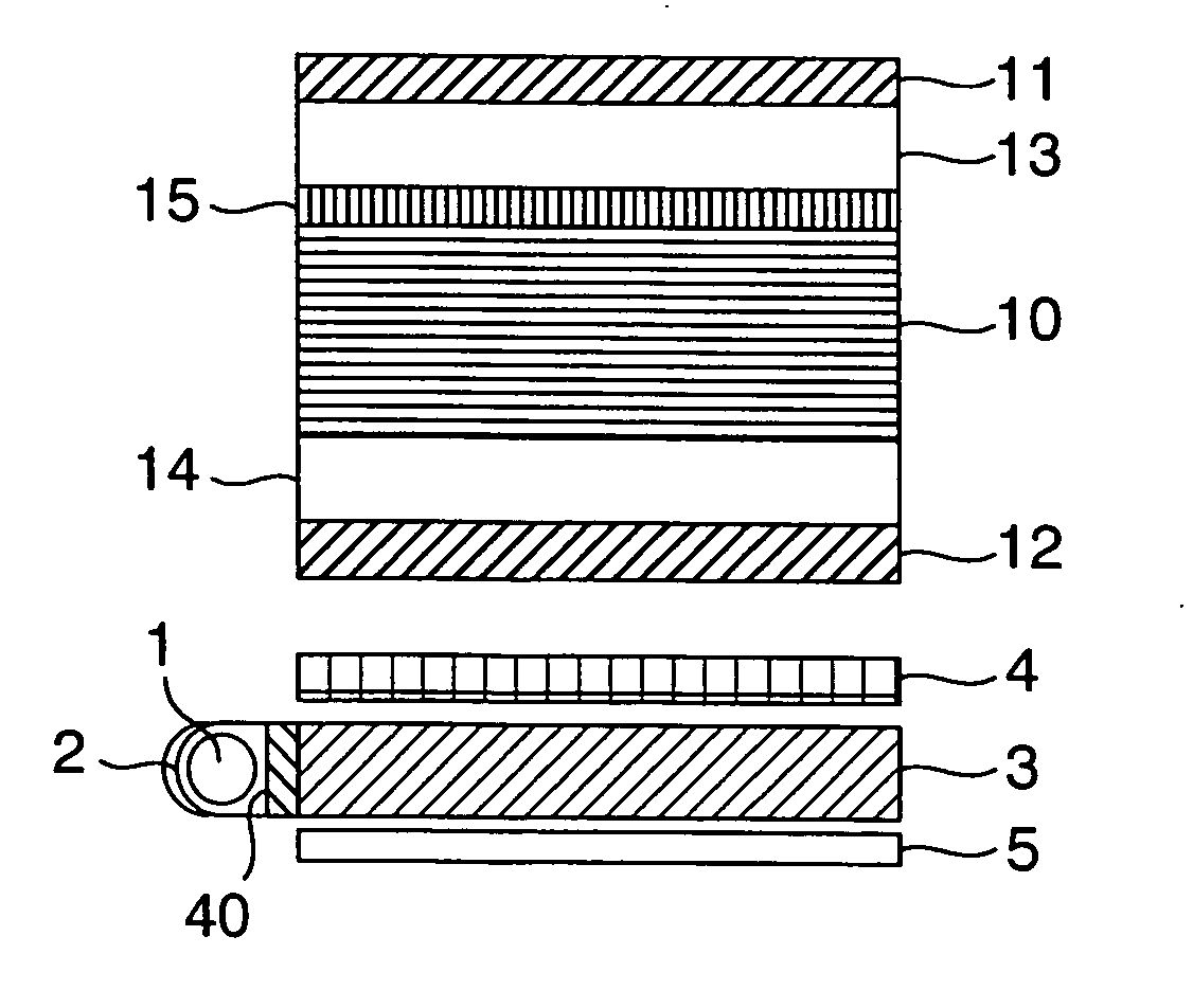
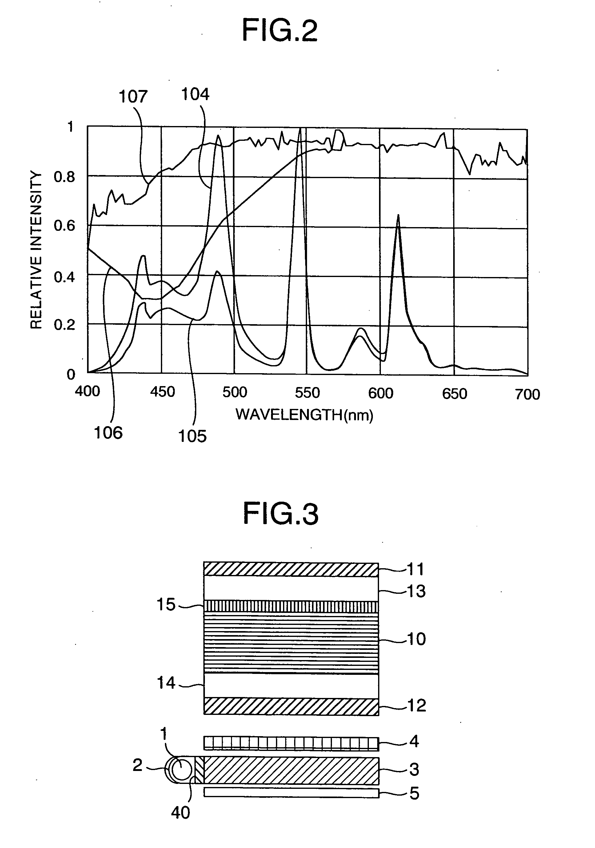
[0056]FIG. 3 schematically shows a cross-sectional view of a liquid crystal display according to the present invention.

[0057] A light source unit disposed in a rear surface of an LCD panel of the first embodiment includes a light source 1, a light cover 2, a light guide 3, a diffuser 4, and a reflector 5. Although not shown, an adhesion layer is formed to prevent loss of light by a layer of air between the light guide 3 and the diffuser 4. A prism sheet may be disposed between the diffuser 4 and a polarizer 12, which will be described later. There may be employed a configuration including a phase plate, not shown, between the polarizers 11 and 12 and substrates 13 and 14 adjacent thereto. The phase plate is employed to improve picture quality of a liquid crystal display depending on cases. Specifications of the phase plate are determined according to purposes of use thereof. The effect and the object of the present invention are independent of presence or absence of arrangement of ...

second embodiment

[0071]FIG. 9 shows, in a cross-sectional view, an example of a configuration of a liquid crystal display in an embodiment according to the present invention.

[0072] A light source unit disposed on a rear surface of an LCD panel of the second embodiment includes a light source 1, a housing unit 6 to house the light source 1, a diffuser 4, and a reflector 5. Although not shown, a prism sheet may be disposed between the diffuser 4 and a polarizer 12, which will be described later. The configuration may also include a phase plate, not shown, between the polarizers 11 and 12 and substrates 13 and 14 adjacent thereto. The phase plate is employed to improve picture quality of a liquid crystal display depending on cases. Specifications of the phase plate are determined according to purposes of use thereof. The effect and the object of the present invention are independent of presence or absence of arrangement of the phase plate. Therefore, the present invention is not restricted by presence...

third embodiment

[0082] The third embodiment includes an LCD panel and the light source unit which are substantially equal in the configuration to the associated constituent components of the second embodiment. These embodiments differ from each other in the arrangement of the spectrum absorber. In the third embodiment, the spectrum absorber is arranged on an upper surface of the polarizer 11 of FIG. 9. In this case, the spectrum absorber 40 is formed, for example, by mixing pigment NK2071, one weight percentage aqueous solution of polyvinyl alcohol having a mean molecular weight of 1000, and methanol with each other at 0.025:0.8:1. The upper surface of the polarizer is then coated with the mixed solution by a spinner (for about three seconds at 350 rpm and for about 25 seconds at 1500 rpm). The substrate is dried at 100° for five minutes on a hot plate to produce a spectrum absorber coated with an about 0.2 μm thick PVA film including a pigment. This method is only an example of production of a spe...


PUM

PropertyMeasurementUnit
wavelength rangeaaaaaaaaaa
wavelengthaaaaaaaaaa

Abstract

A normally-closed liquid crystal display includes a component to selectively absorb characteristic leakage light occurring at black representation. Therefore, when black is displayed, occurrence of unnecessary leakage light due to partial depolarization of polarized light caused by a component of an LCD panel can be suppressed. It is therefore possible to provide a liquid crystal display in which display performance of black is improved to clearly display black.

Description

BACKGROUND OF THE INVENTION [0001] The present invention relates to a liquid crystal display (LCD) and an LCD panel which each include a component to absorb light having a particular wavelength. [0002] A liquid crystal display is advantageous in that the display can be thinner and lighter than a Cathode Ray Tube (CRT generally called a Braun Tube in many cases). Therefore, usage thereof becomes wider with development and advance of a viewing angle widening technology and a mobile picture technology. [0003] With widening uses of a monitor for a desktop personal computer or for a printing and designing jobs and for a liquid crystal television set, demands for color purity of blue, green, and red as well as for color reproduction of gray scale such as a color of skin of a human have become stronger. This leads to application of color filters to increase color purity of three primary colors as a basis of the color reproduction. As for a technique to use color filters, for example, JP-A-...

Claims


Application Information

Patent Timeline
Patent Type & Authority Applications(United States)
IPC IPC(8): G02F1/1333G02F1/1335G02F1/13357G02F1/1343G02F1/1368G02F1/139
CPCG02F1/133514G02F1/133707G02F2203/04G02F1/1393G02F1/134363G02F1/1335
Inventor UTSUMI, YUKASUGIBAYASHI, MAKIKOHIYAMA, IKUOKONDO, KATSUMIMAEHARA, MUTSUMI
Owner PANASONIC LIQUID CRYSTAL DISPLAY CO LTD
Why Eureka
Try Eureka