Liquid crystal display device and method for manufacturing liquid crystal display device

a liquid crystal display device and liquid crystal display technology, which is applied in the direction of optics, non-linear optics, instruments, etc., can solve the problems of reducing the contrast ratio of the liquid crystal display device, affecting the effect of image sticking and staining, and affecting the appearance of liquid crystal panels. , to achieve the effect of reducing the voltage holding ratio, and reducing the generation of image sticking and stain

Active Publication Date: 2021-04-15
SHARP KK
View PDF0 Cites 0 Cited by
  • Summary
  • Abstract
  • Description
  • Claims
  • Application Information

AI Technical Summary

Benefits of technology

[0062]The liquid crystal display device of the present invention according to the above features includes a photo-alignment film containing a polymer that contains a photo-reactive functional group, as well as the aforementioned polymer layer between the liquid crystal layer and the photo-alignment film. Thus, the liquid crystal display device is capable of maintaining a favorable voltage holding ratio and reducing generation of image sticking and stain and a decrease in contrast ratio in a high-temperature environment for a long time.
[0063]The method for manufacturing a liquid crystal display device of the present invention according to the above features includes forming a photo-alignment film containing a polymer that contains a photo-reactive functional group, as well as forming the aforementioned polymer layer between the photo-alignment film and the liquid crystal layer by thermal polymerization. Thus, the method can provide a liquid crystal display device capable of maintaining a favorable voltage holding ratio and reducing generation of image sticking and stain and a decrease in contrast ratio in a high-temperature environment for a long time.

Problems solved by technology

However, since the number of the conductive lines and the area of the black matrix disposed in the liquid crystal panel have been increased, irregularities are now more likely to occur on the substrate surfaces in the liquid crystal panel.
With irregularities on the substrate surfaces, the portions near the irregularities may not be properly rubbed by the rubbing method.
Such a non-uniform alignment treatment may cause a decrease in the contrast ratio in the liquid crystal display device.
However, conventional liquid crystal display devices may suffer display defects such as image sticking and stain, and there is a need for reduction of such defects.

Method used


Image

  • Liquid crystal display device and method for manufacturing liquid crystal display device
  • Liquid crystal display device and method for manufacturing liquid crystal display device
  • Liquid crystal display device and method for manufacturing liquid crystal display device

Examples


synthesis example 1

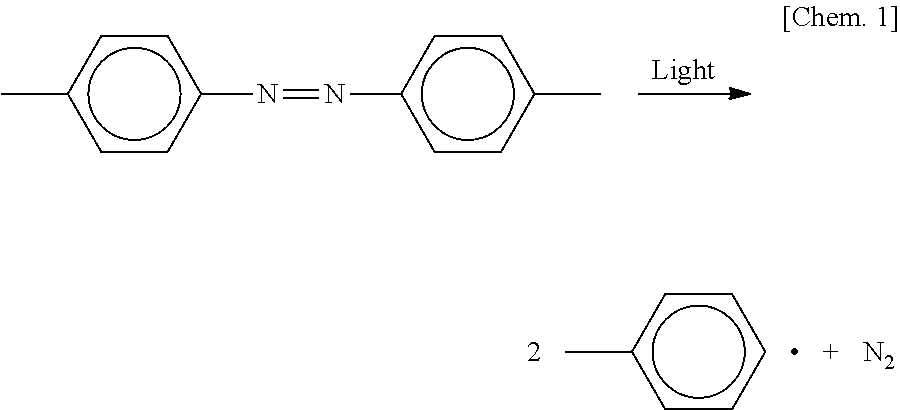
[0200]An N,N-dimethylformamide (DMF) solution (3 mL) containing 10 g (35.7 mmol) of 4,4′-azobis(4-cyanovaleric acid) represented by the following formula (a) was dropwise added to thionyl chloride (10 mL), and the components were stirred at 0° C. for four hours. The thionyl chloride was then removed under reduced pressure, and thereby a solid powder of 4,4′-azobis(4-cyanovaleric acid chloride) represented by the following formula (b) was obtained. The solid powder of the following formula (b) was dissolved in 300 mL of dried tetrahydrofuran (THF). Thereto was added 100 mL of a dried THF solution containing 4.5 g (31 mmol) of hydroxypropyl methacrylate represented by the following formula (c) and 4 g (51 mmol) of pyridine, and the components were stirred at 0° C. for five hours. Then, the THE was removed and the resulting crude crystal was dissolved in diethyl ether. The solution was washed with an aqueous solution of sodium hydrogen carbonate, followed by anhydrous sodium sulfate. T...

example 1

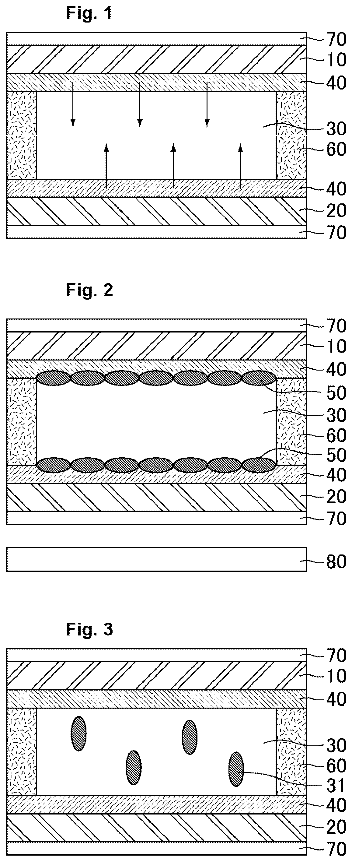
[0201]An FFS-mode liquid crystal cell was actually produced as follows.

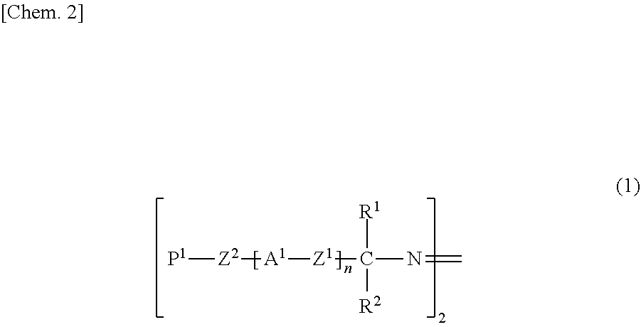
[0202]First, an ITO substrate provided with an FFS electrode structure formed of indium tin oxide (ITO) and a counter substrate provided with no electrode were prepared. Also, a liquid crystal alignment agent was prepared containing a polyamic acid (initial chemical imidization rate: 0%) that is represented by the following formula (A-1) and contains an azobenzene group in the main chain and a polyamic acid (initial chemical imidization rate: 0%) that contains no azobenzene group. In the polyamic acid represented by the following formula (A-1), X4 is a structure represented by the following formula (X4-1); and Y4 is an azobenzene group-containing unit represented by the following formula (Y4-1) or a unit represented by the following formula (Y4-2), with the azobenzene group-containing unit represented by the following formula (Y4-1) and the unit represented by the following formula (Y4-2) being introduced at a ra...

example 2

[0218]An FFS-mode liquid crystal cell of Example 2 was produced in the same manner as in Example 1, except that a polyamic acid (initial chemical imidization rate: 0%) represented by the formula (A-1) and containing an azobenzene group in the main chain (not containing a unit represented by (Y4-2) but containing an azobenzene group-containing unit represented by (Y4-1) alone as Y4) was used instead of the polyamic acid used in Example 1.

[0219]For the FFS-mode liquid crystal cell produced in Example 2, the same evaluation test as in Example 1 and other examples were performed. The results are shown in the following Table 2.

TABLE 2Before testAfter 5000-hour testVHR (%)Contrast ratioVHR (%)Contrast ratioExample 298.1115096.51060Example 198.4110095.31030

[0220]As shown in Table 2, the amount of the azobenzene groups which are photo-reactive functional groups of the polyamic acid-based photo-alignment films in Example 2 was double the amount thereof in Example 1. In comparison with Exampl...


PUM

PropertyMeasurementUnit
wavelengthaaaaaaaaaa
angleaaaaaaaaaa
angleaaaaaaaaaa

Abstract

The present invention provides a liquid crystal display device capable of maintaining a favorable voltage holding ratio and reducing occurrence of image sticking and stain and a decrease in contrast ratio in a high-temperature environment for a long time while including a photo-alignment film, and a method for manufacturing such a liquid crystal display device. The liquid crystal display device of the present invention includes paired substrates, a liquid crystal layer disposed between the substrates, a photo-alignment film disposed between at least one of the substrates and the liquid crystal layer, and a polymer layer disposed between the liquid crystal layer and the photo-alignment film. The photo-alignment film contains a polymer that contains a photo-reactive functional group. The polymer layer contains a polymer that has a structure derived from a specific polymerization initiator and a structure derived from a specific monomer.

Description

TECHNICAL FIELD[0001]The present invention relates to liquid crystal display devices and methods for manufacturing a liquid crystal display device. More specifically, the present invention relates to a liquid crystal display device configured to control the alignment of liquid crystal molecules with a photo-alignment film and a method for manufacturing a liquid crystal display device.BACKGROUND ART[0002]Liquid crystal display devices are display devices utilizing a liquid crystal composition for display. The typical display mode thereof is irradiating a liquid crystal panel containing a liquid crystal composition sealed between paired substrates with backlight illumination and applying voltage to the liquid crystal composition to change the alignment of liquid crystal molecules, thereby controlling the amount of light passing through the liquid crystal panel. Such liquid crystal display devices have features including a thin profile, light weight, and low power consumption, and have...

Claims


Application Information

Patent Timeline
Patent Type & Authority Applications(United States)
IPC IPC(8): G02F1/1337G02F1/1341C08F220/20C08F220/36
CPCG02F1/133711G02F1/133788G02F1/133738G02F2202/42G02F1/1341C08F220/20C08F220/36G02F1/133742C08F222/1025G02F1/133723
Inventor MIZUSAKI, MASANOBUTSUCHIYA, HIROSHI
Owner SHARP KK
Why Eureka
Try Eureka