

Liquid crystal display device
a liquid crystal display and display screen technology, applied in liquid crystal compositions, instruments, chemistry apparatus and processes, etc., can solve the problems of reducing the contrast ratio of the liquid crystal display device, the inability to appropriately rub the steps, and the inability to prevent the occurrence of image sticking and staining on the display screen. , to achieve the effect of preventing the occurrence of image sticking and staining, preventing the voltage holding ratio, and good voltage holding ratio
- Summary
- Abstract
- Description
- Claims
- Application Information
AI Technical Summary
Benefits of technology
Problems solved by technology
Method used
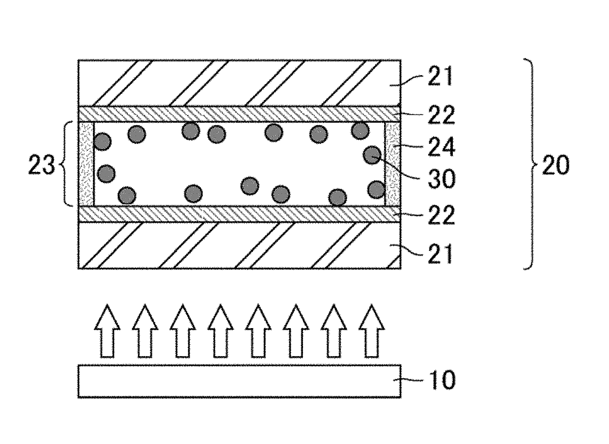
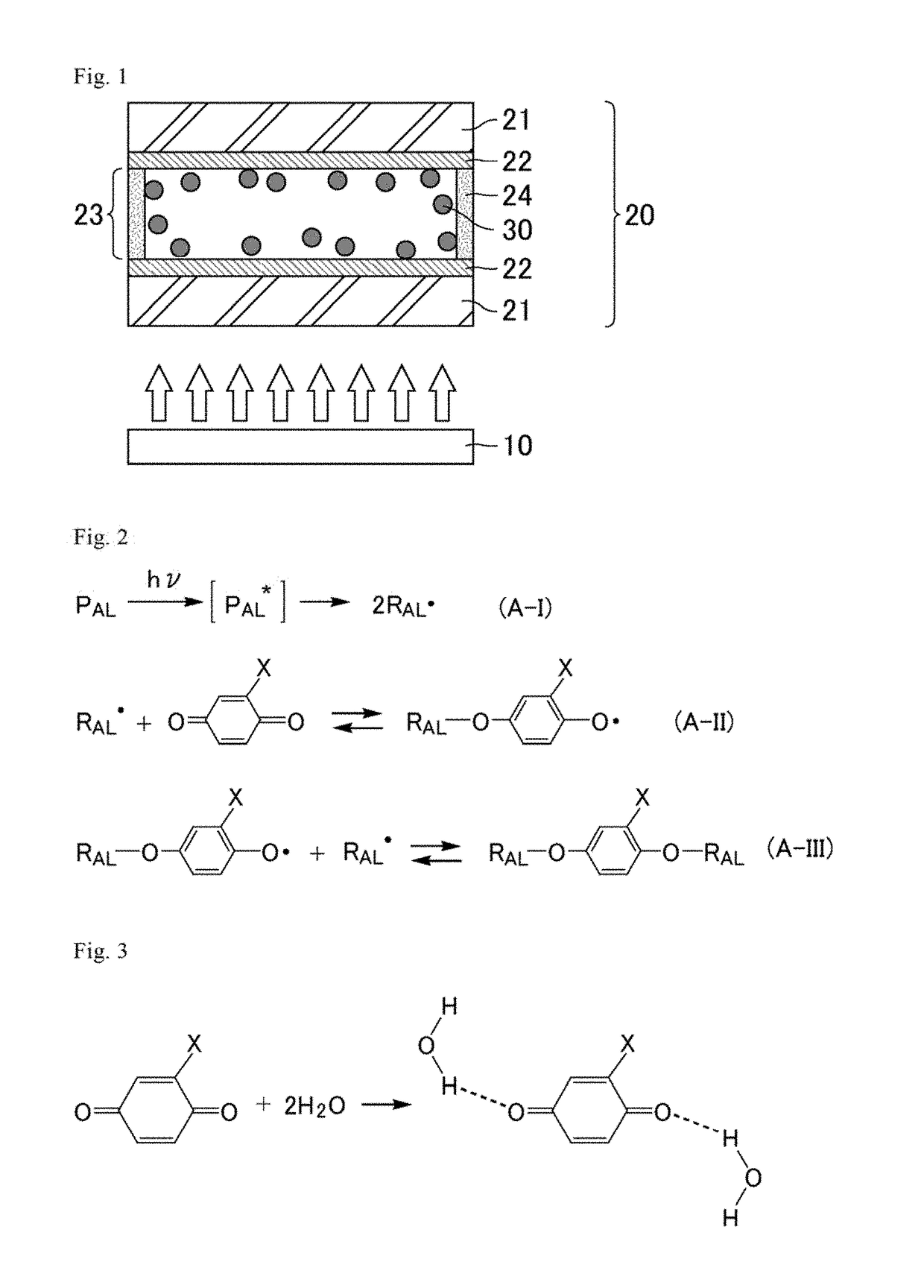
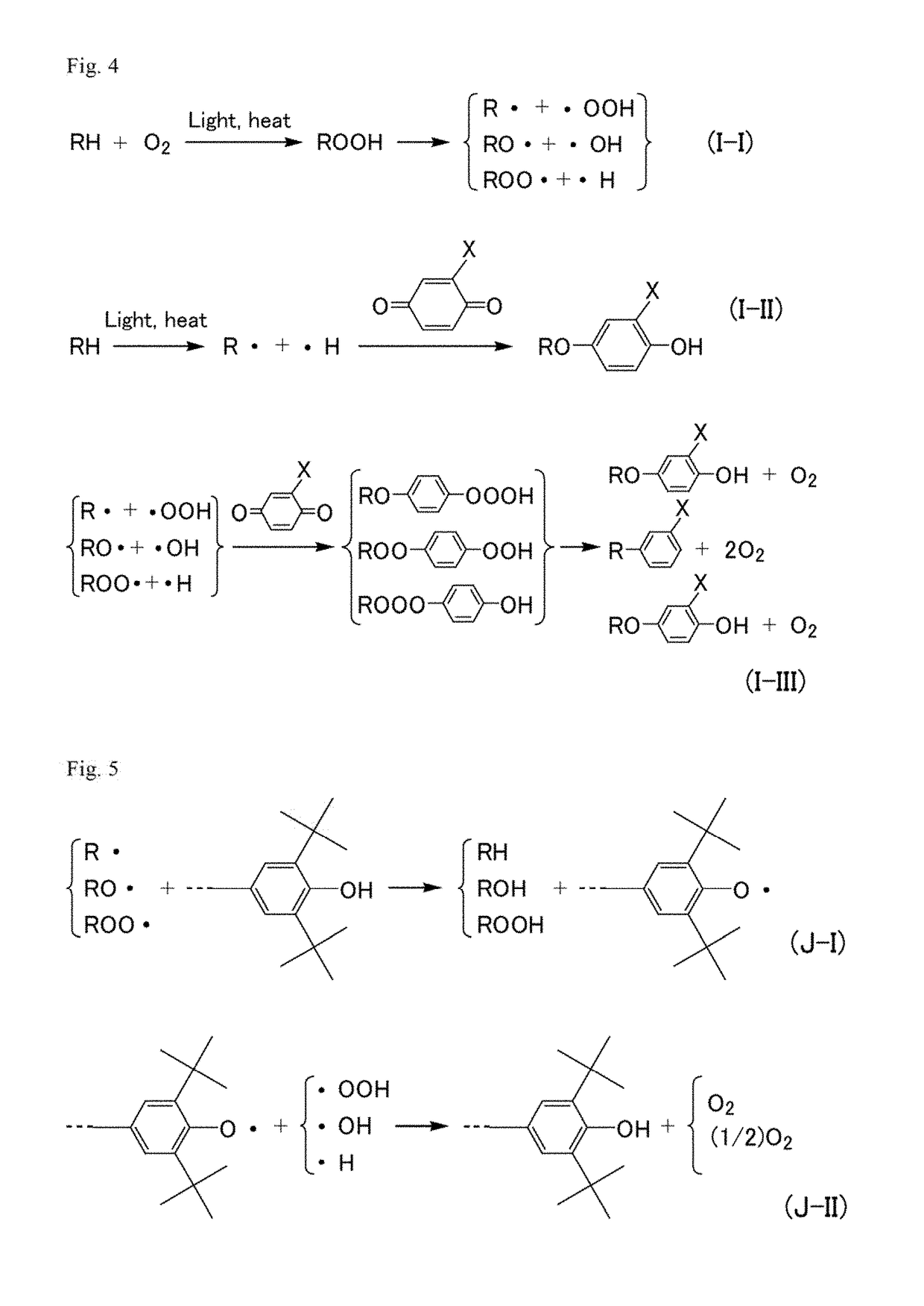
Image

Examples
example 1
[0089]A liquid crystal display device including a liquid crystal panel of a 4-domain reverse TN mode (4D-RTN mode) was actually produced by the following method.
[0090]First, a TFT substrate including TFTs, pixel electrodes, and so forth, and a CF substrate including a black matrix, color filters, a common electrode, and so forth were prepared. Then, an alignment film solution was applied to the surface of each of the TFT substrate and the CF substrate. A solid component of the alignment film solution was a polymer material including a polysiloxane structure as a main skeleton and cinnamate groups represented by a formula (B-1) below serving as photofunctional groups as side chains, and a polyamic acid.
[0091]Next, both the substrates were heated at 80° C. to volatilize the solvent in the alignment film solution. Subsequently, both the substrates were heated at 230° C. for post-baking. In the post-baking, imidization (dehydration cyclization reaction) occurred in part of a polyamic ac...
example 2
[0102]A liquid crystal display device including a liquid crystal panel for the 4D-RTN mode was actually produced in the same manner as in Example 1. The same solid component as in Example 1 was used for the alignment film solution.
[0103]The alignment film solution was applied to the surface of each of the TFT substrate and the CF substrate, and then both the substrates were heated at 80° C. to volatilize the solvent in the alignment film solution. Subsequently, both the substrates were heated at 230° C. for post-baking. Then, as photo-alignment treatment, the surfaces of both the substrates were irradiated with linearly polarized light having a main wavelength of 313 nm at an intensity of 20 mJ / cm2. The direction of polarization of the linearly polarized light was set to be inclined by 40° with respect to a surface on which the alignment film solution was applied. In this way, vertical alignment films in which a sufficient alignment regulating power was developed by the irradiation ...
example 3
[0109]A liquid crystal panel of the fringe field switching mode (FFS mode) was actually produced by the following method.
[0110]First, a TFT substrate including TFTs, an FFS electrode structure, and so forth, and a color filter substrate (CF substrate) including a black matrix, color filters, and so forth were prepared. Then, an alignment film solution was applied to the surface of each of the TFT substrate and the CF substrate. A solid component of the alignment film solution was a polymer material including a polyamic acid structure and an azobenzene structure having a photo-alignment characteristic in the main chain.
[0111]Next, both the substrates were heated at 70° C. to volatilize the solvent in the alignment film solution. Subsequently, as photo-alignment treatment, the surfaces of both the substrates were irradiated with linearly polarized light having a main wavelength of 365 nm at an intensity of 2000 mJ / cm2. The polarization direction of the linearly polarized light was set...
PUM
| Property | Measurement | Unit |
|---|---|---|
| angle | aaaaa | aaaaa |
| angle | aaaaa | aaaaa |
| pre-tilt angle | aaaaa | aaaaa |
Abstract
Description
Claims
Application Information