Liquid crystal display device and method for producing liquid crystal display device

a liquid crystal display and liquid crystal technology, applied in liquid crystal compositions, instruments, chemistry apparatus and processes, etc., can solve problems such as image sticking due to the decrease of vhr, affecting the production efficiency affecting the quality of liquid crystal display devices, so as to reduce the residual dc voltage and the effect of favorable voltage holding ratio

Active Publication Date: 2019-07-25
SHARP KK
View PDF0 Cites 0 Cited by
  • Summary
  • Abstract
  • Description
  • Claims
  • Application Information

AI Technical Summary

Benefits of technology

[0013]The present invention achieves a liquid crystal display device capable of maintaining a favorable voltage holding ratio and reduced residual DC voltage for a long period of time.

Problems solved by technology

Such a liquid crystal display device therefore causes a throughput decrease due to excessively long ultraviolet light irradiation duration and, simultaneously, the voltage holding ratio (VHR) decreases and the residual DC (rDC) voltage increases after long-term use of the liquid crystal display device due to the increased ultraviolet light irradiation dose, thereby decreasing the reliability.
These undesirable changes are caused by radicals generated from polymerizable monomers remaining slightly in the liquid crystal layer.
The studies, however, found that as the amount of the initiator monomer introduced into the liquid crystal material increases, the concentration of impurities from the initiator monomer increases, causing image sticking due to the VHR decrease and the residual DC voltage increase.

Method used


Image

  • Liquid crystal display device and method for producing liquid crystal display device
  • Liquid crystal display device and method for producing liquid crystal display device
  • Liquid crystal display device and method for producing liquid crystal display device

Examples


embodiment 1

[0022]The present embodiment is summarized first. The present embodiment takes the following measures (1) and (2) to overcome the above issues.

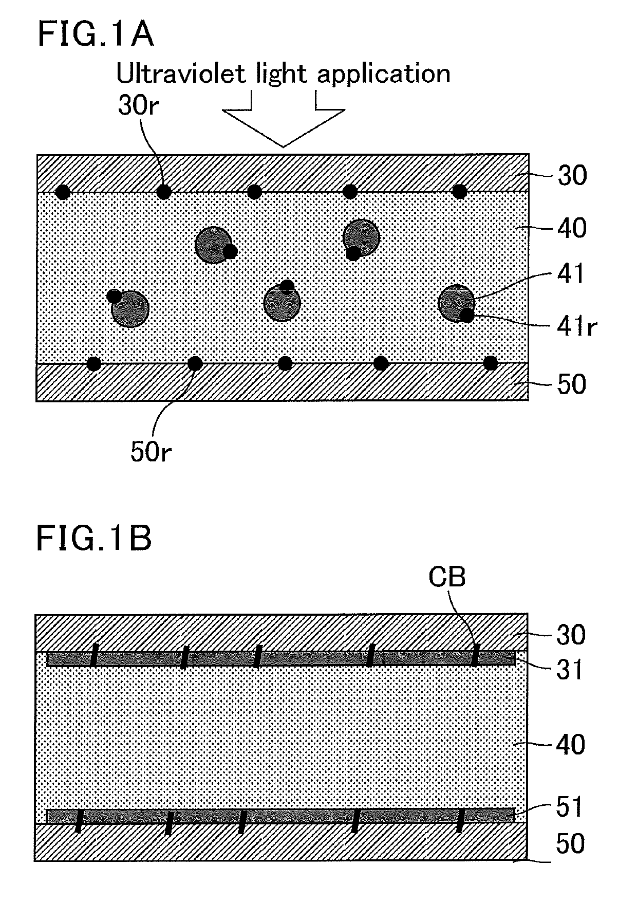
[0023](1) A polymer constituting an alignment film is chemically modified with (covalently bonded to) a functional group capable of initiating radical polymerization under light (hereinafter, also referred to as an initiator functional group).

[0024]In this measure, a polymerization initiator or an initiator monomer is not introduced into the liquid crystal layer, and the moiety functioning as a polymerization initiator can be immobilized on an alignment film surface. This prevents the polymerization initiator components from remaining in the liquid crystal layer, reducing generation of image sticking due to polymerization initiator components. Also, just adding a low molecular weight polymerization initiator into an alignment film may not be enough to prevent the polymerization initiator, which has a low molecular weight, from dissolving in t...

synthesis example 1

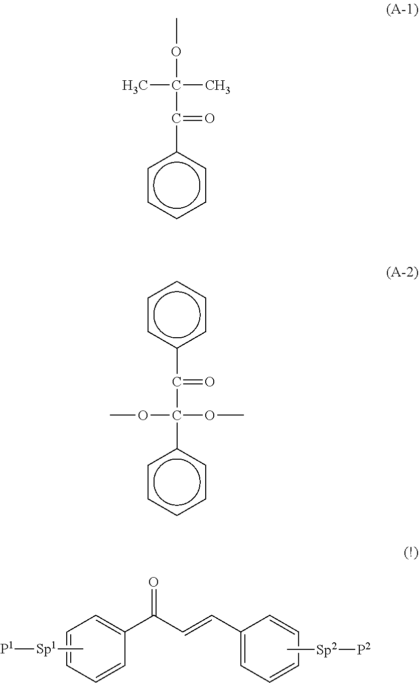
[0088]The following shows an exemplary synthesis of a diamine monomer containing a 2-hydroxy-2-methyl-1-phenyl-propan-1-on functional group in a side chain.

[0089]Process A

[0090]An amount of 3 g of dinitrophenyl acetate (13.3 mmol, compound (1)) was dissolved in 8 mL of SOLMIX AP-I, followed by addition of 0.06 g of Raney Ni to the solution. The mixture was fed into an autoclave. The system was purged with hydrogen and left to stand overnight at room temperature under a pressure of 0.4 MPa. High performance liquid chromatography (HPLC) was used to confirm that the reaction was completed, and then the reaction liquid was filtered through Celite. The filtrate was concentrated until no filtrate was observed. The thus-obtained crude liquid was distilled under reduced pressure, so that 1.98 g of 2,4-diaminophenyl acetate (2) (11.9 mmol, yield: 90%) was obtained. Then, 1.8 g of the compound (2) (10.8 mmol) was dissolved in 5 mL of acetone, followed by dropwise addition of t-butoxycarbonyl ...

synthesis example 2

[0102]The following shows an exemplary synthesis of a diamine monomer containing a benzyl ketal-based initiator in a side chain.

[0103]Process A

[0104]A benzene solution (5 mL) containing 0.64 g (2.5 mmol) of benzyl dimethyl ketal represented by the following formula (2) was dropwise added into a benzene solution (20 mL) containing 0.42 g (2.5 mmol) of ethyl 4-hydroxybenzoate (the following formula (1)) and 0.5 g (5 mmol) of triethylamine at room temperature in a nitrogen atmosphere. The mixture was reacted at room temperature for two hours. After completion of the reaction, the impurities were extracted with water, and the residue was purified by column chromatography (toluene / ethyl acetate (4 / 1)), whereby 0.878 g (yield: 90%) of the target compound represented by the following formula (3) was obtained.

[0105]Process B

[0106]Into a THF / methanol mixed solution (20 mL) containing 0.78 g (2 mmol) of the compound represented by the formula (3) was dropwise added a sodium hydroxide aqueous ...


PUM

PropertyMeasurementUnit
temperatureaaaaaaaaaa
pre-tilt angleaaaaaaaaaa

Abstract

The present invention provides a liquid crystal display device that includes: a pair of substrates; a liquid crystal layer held between the substrates; an alignment film disposed on a liquid crystal layer side surface of at least one of the substrates; and a polymer layer disposed between the liquid crystal layer and the alignment film, the liquid crystal layer containing liquid crystal compounds aligned in a predetermined direction with no voltage applied, the alignment film containing a first polymer containing in its main chain at least one selected from a polyamic acid structure and a polyimide structure, the first polymer containing a functional group that functions as a polymerization initiator, the polymer layer containing a second polymer obtained by polymerizing at least one monomer containing a chalcone group.

Description

CROSS-REFERENCE TO RELATED APPLICATIONS[0001]The present application claims priority under 35 U.S.C. § 119 to Japanese Patent Application No. 2018-008202 filed on Jan. 22, 2018, the contents of which are incorporated herein by reference in their entirety.BACKGROUND OF THE INVENTIONField of the Invention[0002]The present invention relates to liquid crystal display devices and methods for producing a liquid crystal display device. The present invention specifically relates to a horizontal alignment mode or vertical alignment mode liquid crystal display device including a polymer layer, and a production method thereof.Description of Related Art[0003]Displays such as liquid crystal display devices have spread rapidly and have been used in a wide variety of applications including televisions, electronic book readers, digital photo frames, industrial appliances, personal computers (PCs), tablet PCs, smartphones, and HMDs. Liquid crystal display devices are required to have a variety of pr...

Claims


Application Information

Patent Timeline
Patent Type & Authority Applications(United States)
IPC IPC(8): G02F1/1337G02F1/1343G02F1/1339C09K19/54C09K19/56
CPCG02F1/133723G02F1/134363G02F1/1339C09K19/542C09K19/56G02F2001/134372G02F2001/133397G02F2202/022C09K2019/548G02F1/133711G02F1/133788G02F1/134372C09K2019/0448C09K19/2028G02F1/133703G02F1/133715G02F1/133397C09K2323/00C09K2323/02
Inventor MIZUSAKI, MASANOBU
Owner SHARP KK
Why Eureka
Try Eureka