

Combine harvesters
a harvester and combine technology, applied in the field of combine harvesters, can solve the problems of prone to fall off or be brushed off naturally
- Summary
- Abstract
- Description
- Claims
- Application Information
AI Technical Summary
Benefits of technology
Problems solved by technology
Method used
Image

Examples
Embodiment Construction
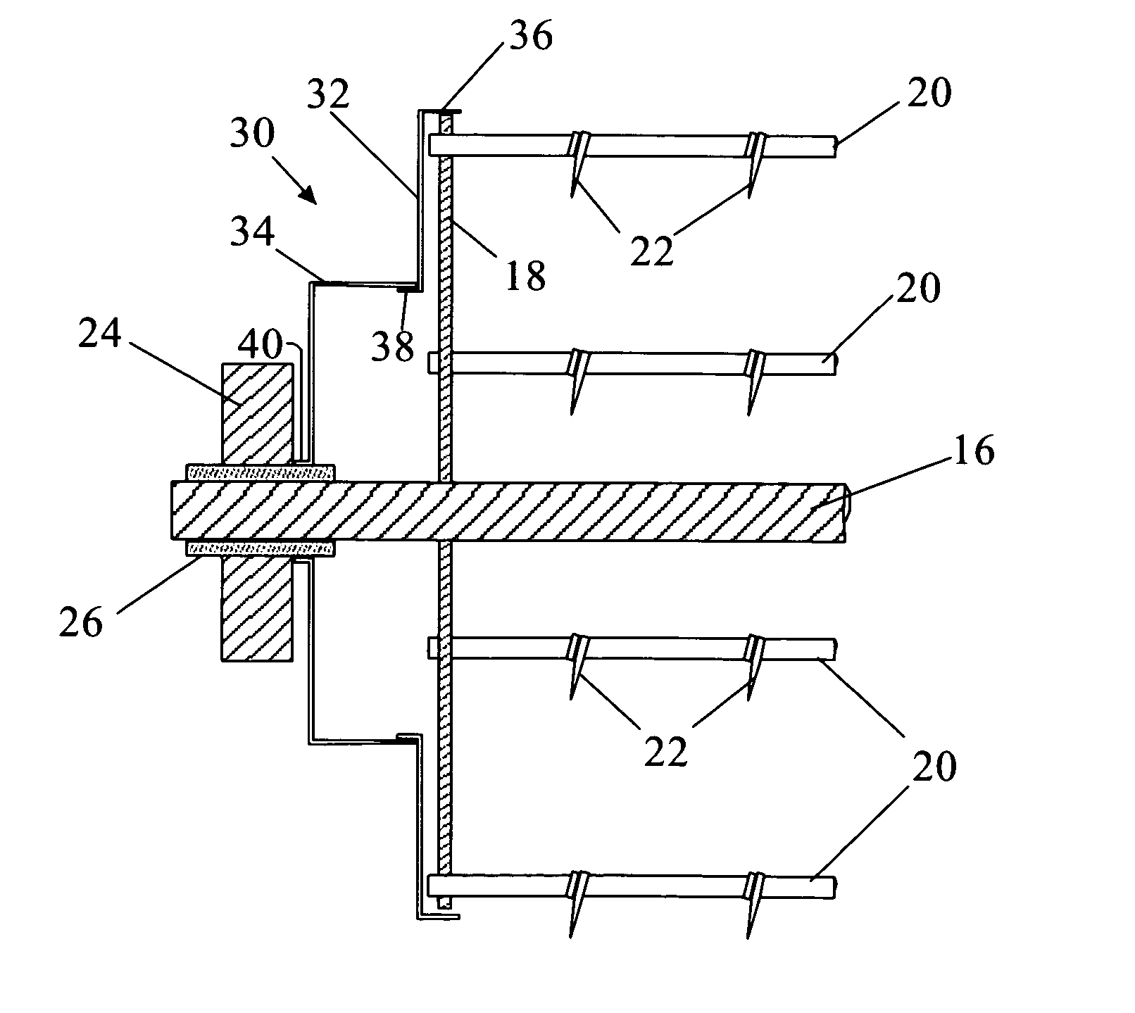
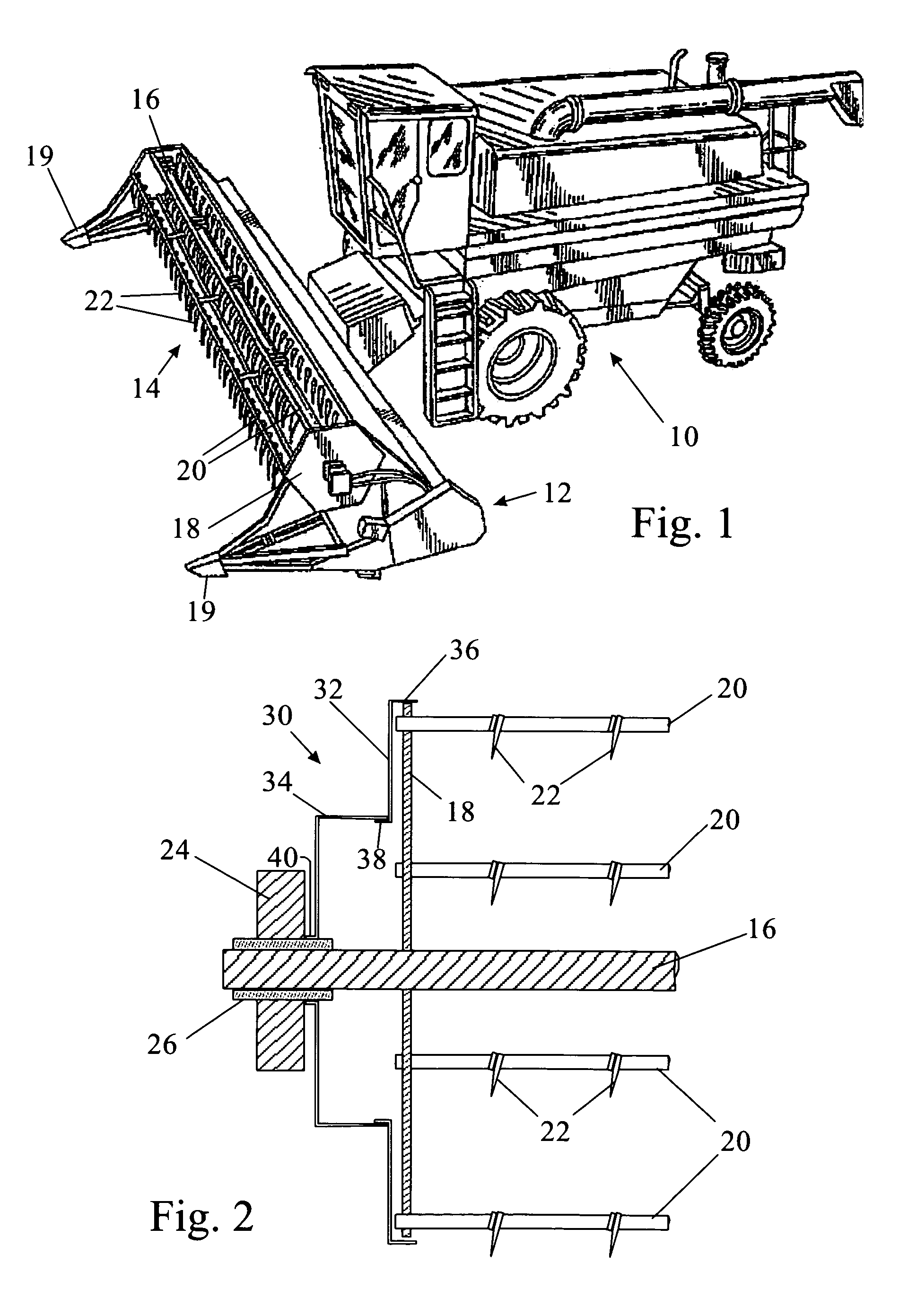
[0016]Referring to FIGS. 1 and 2, a combine 10 is fitted with a header 12 carrying a reel 14 that rotates about a transverse axis. The reel has a central shaft 16 and two hexagonal end plates 18. Bars 20 carrying tines 22 extend between the two end, the tines 22 acting to pull up the crop from the ground. At each end, the central shaft 16 is supported a side arm 24 of the header 12 by means of a journal bearing housing 26. Crop separators 19 project forwards of the reel 14 to demarcate the swathe of land to be harvested.
[0017]Conventionally, various components of the reel 14, such as the fixings attaching the ends of the bars 20 to the hexagonal plates 18, protrude from the plates 18. These act to wrap crop about the section of the shaft 16 between the side arm 24 of the header 12 and the plate 18 and eventually the farmer will need to remove this entangled crop.
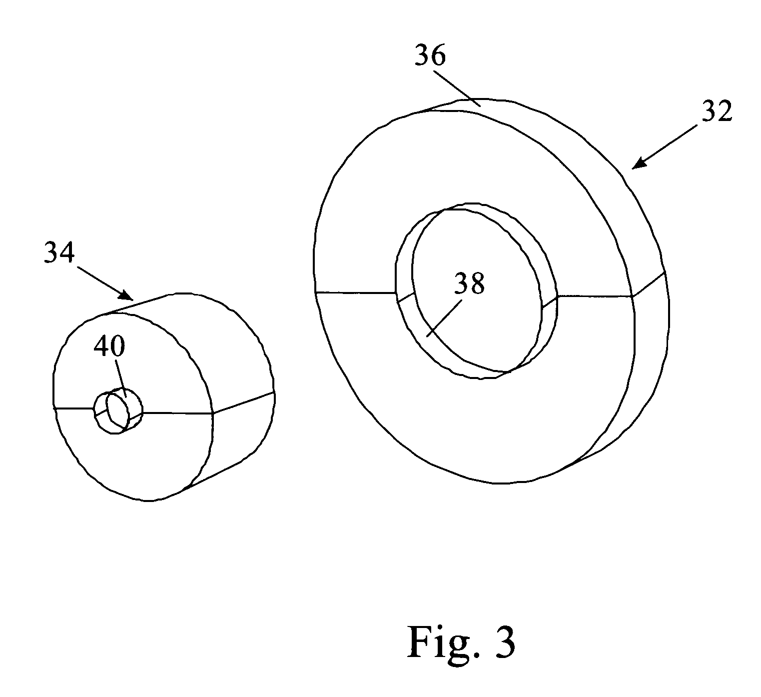
[0018]To overcome this problem, the present invention provides an anti-wrapping device 30 made up of two components that a...
PUM
 Abstract
Description
Claims
Application Information