Release liner staging unit and system incorporating same

a technology of staging unit and release liner, which is applied in the direction of mechanical control devices, instruments, process and machine control, etc., can solve the problems of liner breaking, and achieve the effect of hysteresis and production of saturated levels

Active Publication Date: 2008-10-28
VALCO CINCINNATI
View PDF4 Cites 2 Cited by
  • Summary
  • Abstract
  • Description
  • Claims
  • Application Information

AI Technical Summary

Benefits of technology

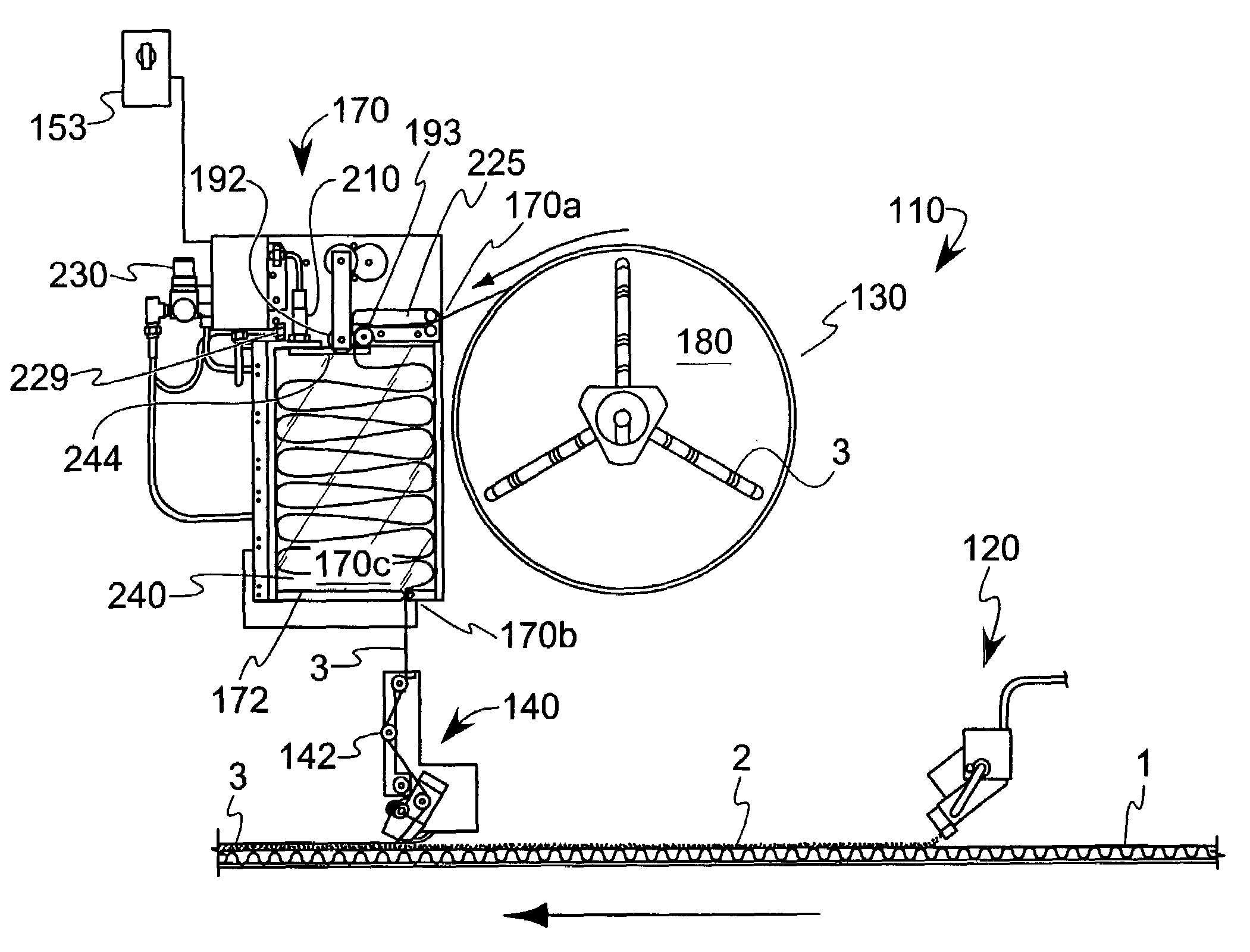
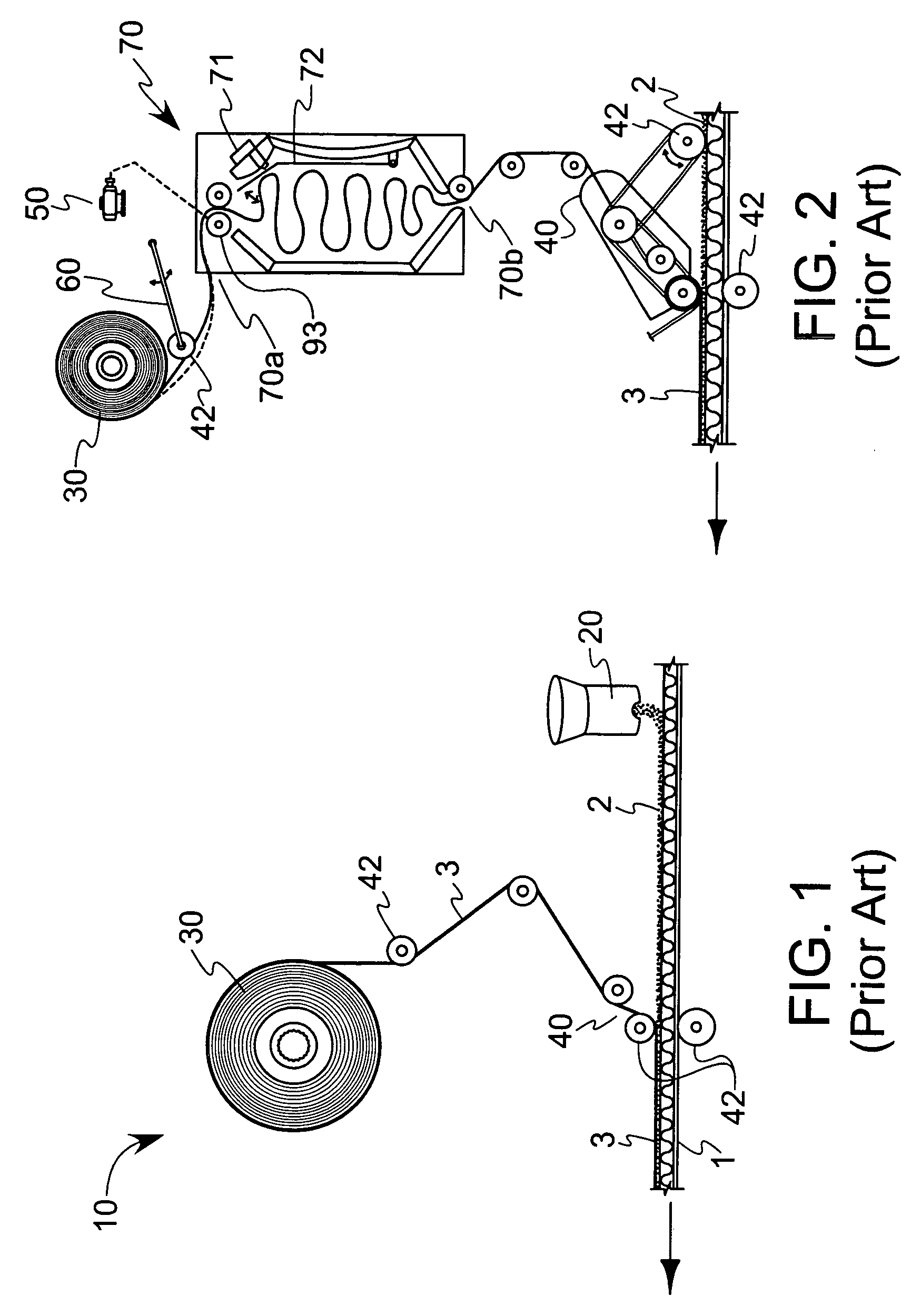
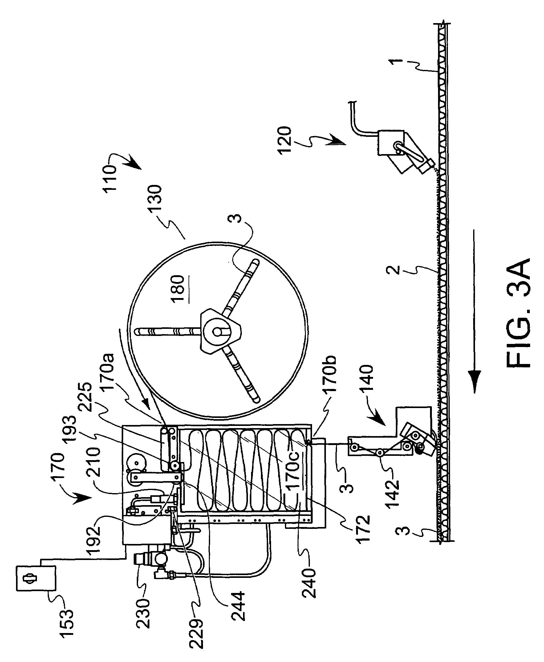
[0006]Optionally, the thickness of the release liner staging unit is only slightly greater than the width of the release liner, thereby inhibiting twisting of the liner when situated in the liner storage compartment. Thus, by limiting the paths for air resident in the accumulator to circulate, this has the additional benefit of forming an air cushion to inhibit the formation of an overly dense stacking of release liner in the accumulator. Furthermore, the width of the unit can be made variable to accommodate release liner of differing widths, where a combination of spacers and panels that mount in the box take up the excess space that would cause the liner disposed in the unit to fall to the side. In addition, the unit may include access regions to facilitate cleaning, threading of the liner or the like. Moreover, anti-static devices (such as tinsel) can be placed at the inlet to prevent static from building up on the roll of web, where static can cause the loops of release liner to not fall into a correct serpentine pattern in the unit due to an adhesion of the release liner to electrically-chargeable plastic components (such as a door) situated at the unit inlet.
[0007]In one form, the release liner advancing member is a drive roller, where a guide plate cooperates with the drive roller. In a particular form, the guide plate comprises at least one projecting finger and the drive roller comprises a complementary groove such that the guide plate and the drive roller cooperate to inhibit wrapping of the release liner around the drive roller. An anti-backlash roller clutch has a rubber-coated non-driven nip roller with the ability to promote adjustable tension. The clutch prevents the roll from rotating backward due to the weight of the full reel of release liner that would otherwise cause the web to create slack and consequent misalignment or breakage on the driven roller. The drive mechanism may include a brake that upon engagement inhibits movement of a liner supply device (the latter of which may be in the form of a spool as discussed below) from coasting. One form of the brake is a pneumatic brake. An air bleed valve can further be included to provide a blast of low-pressure air to keep the release liner tape lower in the unit so that the serpentine loops occur in a more organized fashion, thereby reducing the risk of a double feed through the output slot. In the present context, a double feed occurs when an upstream folded-over portion of the liner gets fed through the outlet along with downstream portions of the liner. Upon dispensing of this upstream portion of the liner, a snapping motion could cause the liner to break.
[0010]In yet another option, the device includes one or more sensors to monitor release liner parameters, such as movement or the presence of the liner. Such sensors can be signally coupled to a controller. In one form, the sensors can monitor for a break in the release liner; upon such sensing and subsequent signal sent the controller, the device can be shut down. A time delay relay may also be included to control the delay between the time that the sensor indicates the presence of release liner in the unit and when a feed motor supplying release liner to the unit is shut off. This delay allows the unit to be more densely filled in the accumulator, thus reducing the unit's duty cycle. A pneumatic brake can be included to stop the roll from supplying release liner to the unit, thereby avoiding “coasting” that would otherwise create slack that could break the web when the device starts feeding again. Optionally, the device may further include an air chuck that allows the user to release compressed air for engaging and disengaging the hub holding the reels of release liner.
[0013]According to still another aspect of the invention, a method of reducing inertial effect from a supply of release liner is disclosed. The method includes selectively feeding release liner to an accumulator, storing the release liner in a substantially serpentine pattern in the accumulator, measuring an amount of space in the storage compartment occupied by the release liner and operating a time delay cooperative with the measuring such that after the amount of space occupied by the stored release liner drops below a predetermined threshold, additional release liner is introduced into the accumulator to saturate a level of release liner therein. In one optional form, either a fixed-speed or a variable-speed drive mechanism (for example, a variable speed motor or related means for operating a release liner advancing member) could be incorporated to facilitate feeding release liner to the accumulator. Such a drive mechanism could be similarly used in conjunction with the devices of the previously-described aspects. Use of a variable-speed drive mechanism could promote continuous (rather than stop-start) operation, where a quiescent operating point could be established.

Problems solved by technology

Upon dispensing of this upstream portion of the liner, a snapping motion could cause the liner to break.

Method used


Image

  • Release liner staging unit and system incorporating same
  • Release liner staging unit and system incorporating same
  • Release liner staging unit and system incorporating same

Examples


Embodiment Construction

[0025]Referring first to FIG. 1, an adhesive layer and release liner application system 10 according to the prior art is shown. The system 10 sequentially places an adhesive layer 2 and a release liner 3 onto a moving substrate 1. In one configuration, the adhesive layer 2 is a hot melt adhesive that is deposited in viscous liquid form, while the release liner 3 is a relatively thin (on the order of a few mils or less) film of silicone coated paper or similar non-adherent material. The substrate is a generally planar paper, plastic or cardboard material which, after adhesive deposition, can be folded or stacked for subsequent use. The system 10 includes an adhesive application device 20, spool 30 of release liner and a release liner application device 40 with numerous rollers 42. Adhesive application device 20 typically includes a vat to store the adhesive, as well as related heating devices and conduit to liquefy and transport the adhesive to one or more deposition nozzles.

[0026]Re...


PUM

PropertyMeasurementUnit
shapeaaaaaaaaaa
widthsaaaaaaaaaa
tensionaaaaaaaaaa

Abstract

A release liner staging unit for depositing a release liner onto an adhesive layer. The unit includes an accumulator that creates a buffer between an amount of release liner supplied and an amount needed for covering a layer of adhesive. The tendency of release liner placed within the accumulator to settle allows additional release liner to be introduced, thereby producing a slightly saturated level of release liner in the accumulator. Time delays can be accounted for to reduce the number of times a drive mechanism needs to operate, thereby reducing wear on such componentry. The unit may also form part of a larger release liner application device and adhesive application system.

Description

CROSS-REFERENCE TO RELATED APPLICATIONS[0001]This application is based on U.S. provisional application Ser. No. 60 / 565,646, filed Apr. 27, 2004.BACKGROUND OF THE INVENTION[0002]This invention relates generally to a device for applying a release liner to an adhesive that is disposed on a substrate, and more particularly to an improved accumulator that regulates the tension in the release liner as the liner is being applied.[0003]Automated gluing systems are routinely used to affect high-speed, repeatable application of adhesives to various substrates such that upon contact between the adhesive-containing substrate and another surface, a bond or seal is formed. Such systems are employed in deferred-use packaging, where a pressure-sensitive adhesive is covered with a release liner such that upon subsequent removal of the release liner and placement of the exposed adhesive in contact with a desired surface, the surface on which the adhesive is placed and the desired surface can be joine...

Claims


Application Information

Patent Timeline
Patent Type & Authority Patents(United States)
IPC IPC(8): B32B41/00B32B37/20B32B38/18B65H26/00
CPCB32B38/18B32B37/1284B32B37/20
Inventor MAINOUS, DAVID LEEPOPHAM, DAVID ALLENCHAMBERS, JOHN PAUL G.JAMISON, CHRIS MARK
Owner VALCO CINCINNATI
Why Eureka
Try Eureka