Arrangement for measuring a property of a fluid present in a tube

a technology for measuring apparatus and fluid, which is applied in the direction of liquid/fluent solid measurement, fluid pressure measurement, instruments, etc., can solve the problems of creating additional costs, providing a lateral access opening, and the tube must be completely severed during installation of the shut-off valve, so as to facilitate the manufacture of apparatus and achieve the effect of less cost, simplified manufacturing and simplified arrangemen

Inactive Publication Date: 2007-01-30
GAMBRO LUNDIA AB
View PDF16 Cites 85 Cited by
  • Summary
  • Abstract
  • Description
  • Claims
  • Application Information

AI Technical Summary

Benefits of technology

[0021]In this manner, a simple apparatus is provided, which for example may be used in dialysis monitors, which enables a simple and at the same time reliable seal of the lateral access opening on the tube. With the formation of the domed wall portion in the tube and the arrangement of a seal surface on the outer side of this domed wall portion, a large seal surface is provided that is formed substantially without edges and corners, on which the sensor can be simply disposed in a reliably sealed manner. The sensor is arranged over the lateral access opening, which is arranged in such a way in the seal surface, or which terminates in such a way in the seal surface, that it is surrounded by the seal surface. In this manner, on the one hand, the lateral access opening is simply and reliably sealed by the sensor itself and, on the other hand, the sensor is readily brought into direct contact with the fluid. The sensor thus sits on the seal surface and is simultaneously in direct contact with the fluid.
[0025]In both cases care should be taken that an adequately large domed wall portion is available to provide a sufficiently large seal surface on its outer side. Advantageously, in this case the wall of the tube forms the seal surface, which further facilitates the manufacture thereof.
[0026]The lateral access to the interior of the tube arranged in the seal surface can be formed in any manner. However, it is advantageous, and provided according to a preferred embodiment, when the lateral access opening is formed by levelling away the wall of the tube at the outer side of the domed wall portion along a flat plane. In doing this it is advantageous when the domed wall portion is ground away at its outer side to form the lateral access opening. In this manner, the seal surface will simultaneously be formed with the lateral access so that the manufacture is further simplified and the arrangement becomes altogether less expensive. Moreover, in this manner, a transition between the lateral access opening and the interior of the tube is provided that is favorable to flow, which is of particular advantage when the fluid present in the tube flows.

Problems solved by technology

However, owing to the geometry of the tube it is difficult to provide a lateral access opening that, on the one hand, allows for direct contact of the sensor with the fluid and, on the other hand, is reliably sealed from the surroundings.
A disadvantage of this type of apparatus is that the tube must be completely severed during installation of the shut-off valve.
Moreover, a shut-off valve entails an additional material expense in addition to the supplementary installation expense, thus creating additional costs.
While this makes possible a reliable seal of the temperature sensor from the fluid, this seal also requires a larger amount of labor.
This creates supplementary costs in addition to the required additional material.
However, numerous seal surfaces are necessary, which increases the risk of leaks.
In addition, this known apparatus is also expensive in terms of material and labor and is therefore costly.

Method used


Image

  • Arrangement for measuring a property of a fluid present in a tube
  • Arrangement for measuring a property of a fluid present in a tube
  • Arrangement for measuring a property of a fluid present in a tube

Examples


first embodiment

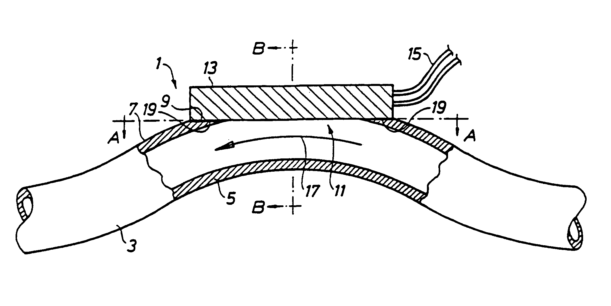
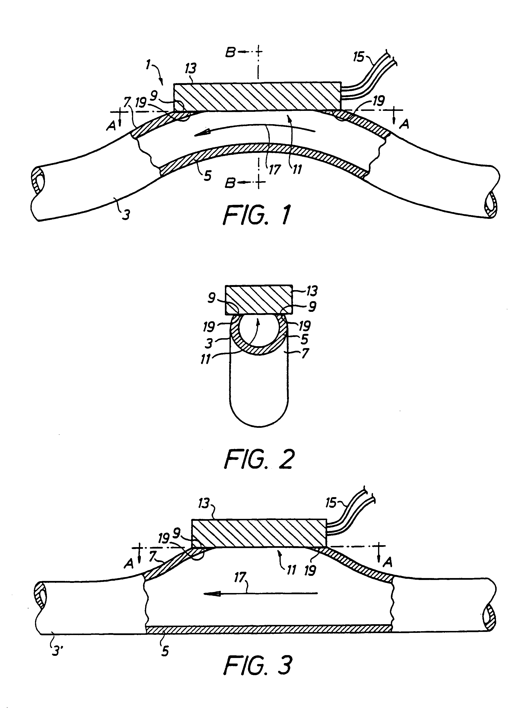
[0036]Referring to the drawings, in which like reference numerals refer to like elements thereof, FIG. 1 shows the measurement apparatus 1 in longitudinal section. The measurement apparatus 1 includes a sensor 13 that is disposed on a tube 3 to measure properties of a fluid 17 present in the tube 3. The fluid 17 can be either stationary in the tube or flow through it.

[0037]The tube 3 comprises a domed wall portion 7 that, in this embodiment, is formed by bending the whole tube 3. On its outer side the domed wall portion 7 there is a seal surface 9, in which a lateral access opening 11 is arranged. In this embodiment, the seal surface 9 is formed together with the lateral access opening 11 by grinding away the outer side of the domed wall portion 7 along a flat plane. This plane is indicated by the dashed and dotted line A—A. The seal surface is thus formed by the ground away portion of the wall 5 of the tube 3. The form of the transition between the lateral access opening 11 and the...

second embodiment

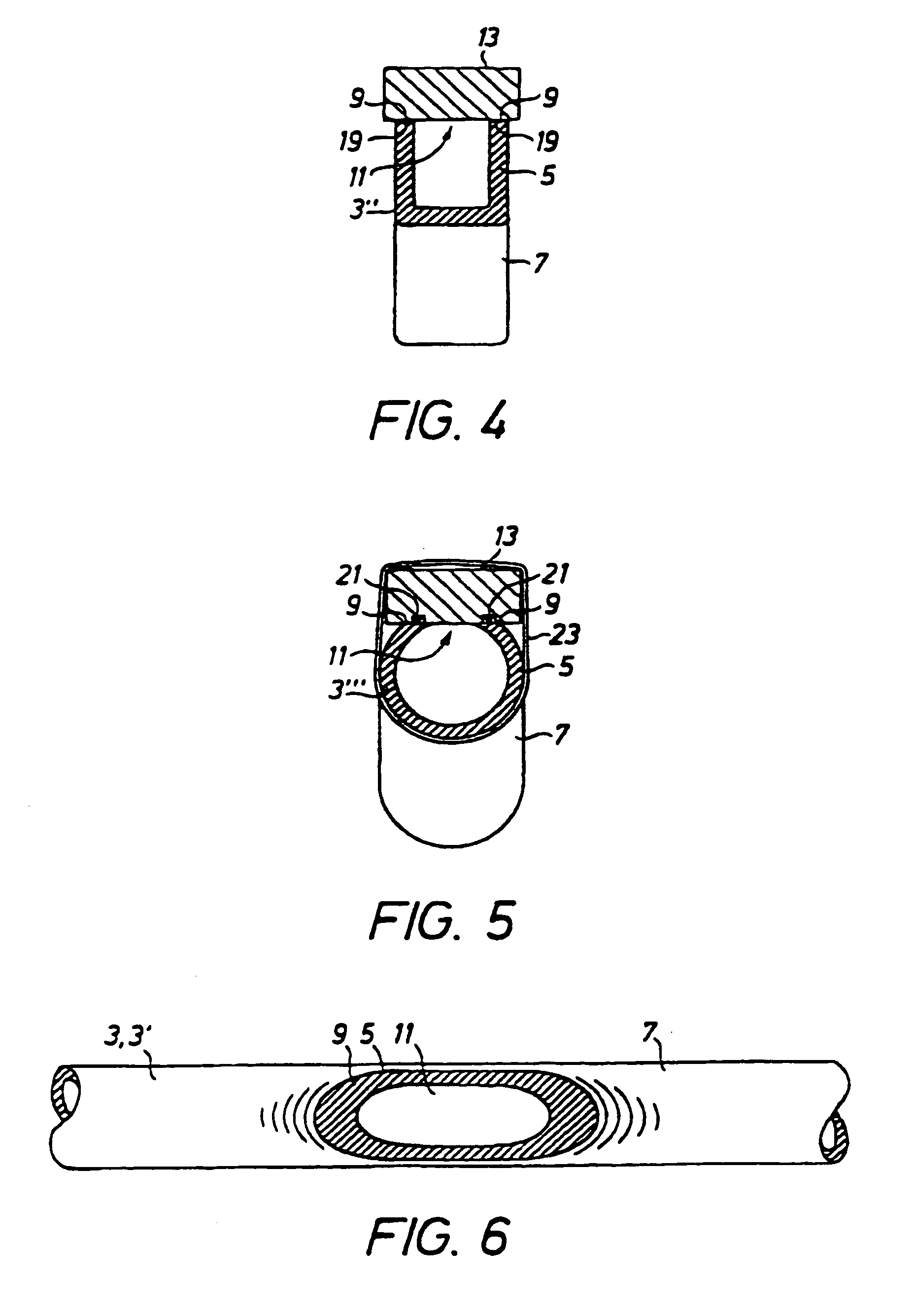
[0042]In FIG. 3 is shown the measurement apparatus in longitudinal section. Like parts are denoted by like reference numerals. The tube 3′ of this embodiment is not bent as a whole to form the domed wall portion 7. Instead, only a region of the wall of the tube 3′ bulges outwardly to form the domed wall portion 7.

[0043]Furthermore, in this case a seal surface 9 that is created by levelling away the outer side of the domed wall surface along a straight line A—A is formed on the outer side of the domed wall portion 7. As mentioned, in this manner the lateral access opening 11 is formed at the same time. The sensor 13 is then, in turn, arranged on the seal surface 9 such that it completely covers, and accordingly seals, the lateral access opening 11, while being simultaneously in direct contact with the fluid 17. A seal between sensor 13 and seal surface 9 is accomplished in this embodiment also by gluing the sensor 13 to the seal surface 9 by means of a suitable adhesive 19. The tube ...


PUM


Abstract

Apparatus for measuring a property of a fluid is provided including a tube for retaining the fluid, the tube including a lateral access opening and a domed portion including a sealing surface on the outside wall of the tube surrounding the lateral access opening and a sensor sealingly disposed on the sealing surface surrounding the lateral access opening in the tube for direct contact with the fluid in the tube for sensing the property of the fluid in the tube.

Description

FIELD OF THE INVENTION[0001]The present invention relates to apparatus for measuring a property of a fluid present in a tube, with a sensor for measuring the desired property, which sensor is disposed on the tube and is in direct contact with the fluid through a lateral access opening.BACKGROUND OF THE INVENTION[0002]Various implementations of apparatus for measuring a property of a fluid present in a tube are known. They are utilized in the most diverse apparatus, for example in dialysis monitors, for measuring any properties of the fluid. To this end, they generally comprise a sensor, which is suitable for measuring the desired property. The measured properties of the fluid are, for instance, the temperature, the flow velocity, the pressure, the conductivity, etc.[0003]However, measuring these properties of the fluid requires the sensor to be in direct contact with the fluid, which is generally established through a lateral access opening, i.e. a lateral opening in the tube. For t...

Claims


Application Information

Patent Timeline
Patent Type & Authority Patents(United States)
IPC IPC(8): G01D21/00
CPCG01N33/487
Inventor DROTT, JOHAN
Owner GAMBRO LUNDIA AB
Why Eureka
Try Eureka