Track suspension device

a technology of suspension device and track, which is applied in the direction of lighting support device, lighting and heating apparatus, walls, etc., can solve the problems of damage to the track surface, inability to adjust the position of suspended items quickly and easily, and inability to quickly and easily adjust the position of suspended items along the track. , to achieve the effect of quick and easy adjustment and simple and sturdy

Inactive Publication Date: 2006-05-18
AIRWALL HANGERS
View PDF11 Cites 15 Cited by
  • Summary
  • Abstract
  • Description
  • Claims
  • Application Information

AI Technical Summary

Benefits of technology

[0005] The principal and secondary objects of this invention are to provide a simple and sturdy attachment device for suspending heavy structures from a ceiling or other undersurface and allowing

Problems solved by technology

Bolts passing through holes in the rail or track and appropriate brackets are commonly used, but do not allow quick and easy transversal adjustment of the position of the suspended items along the track.
Adjustab

Method used


Image

  • Track suspension device
  • Track suspension device
  • Track suspension device

Examples


first embodiment

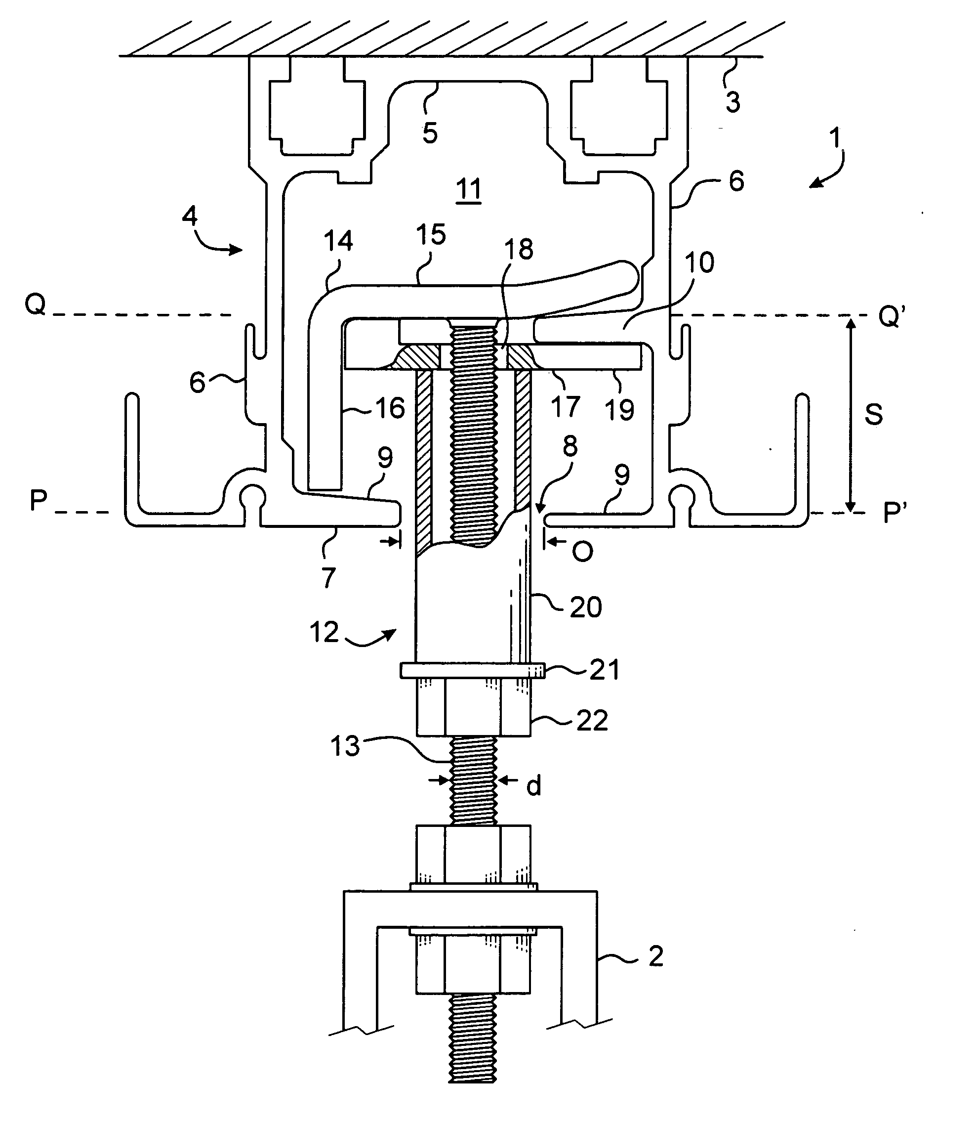
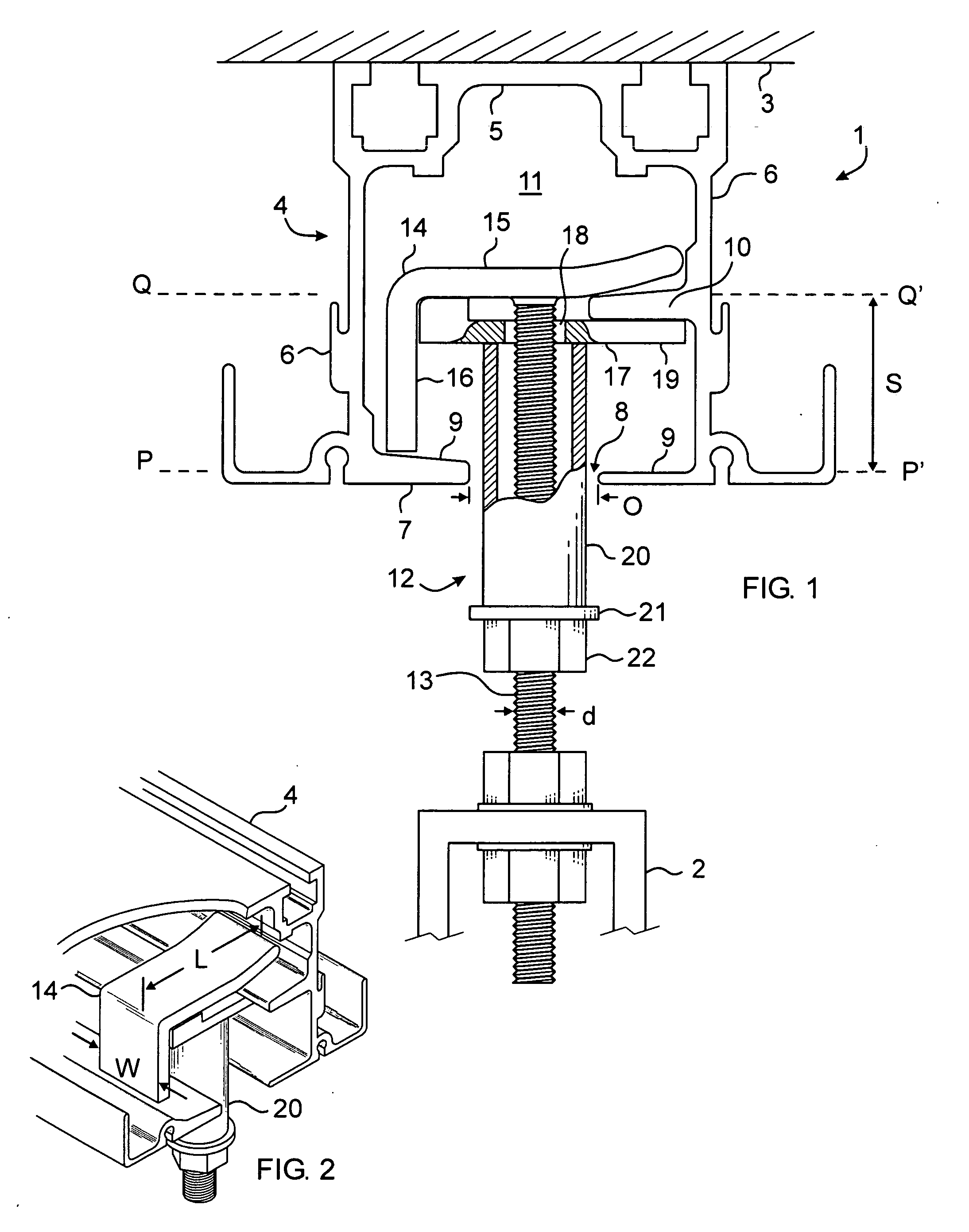
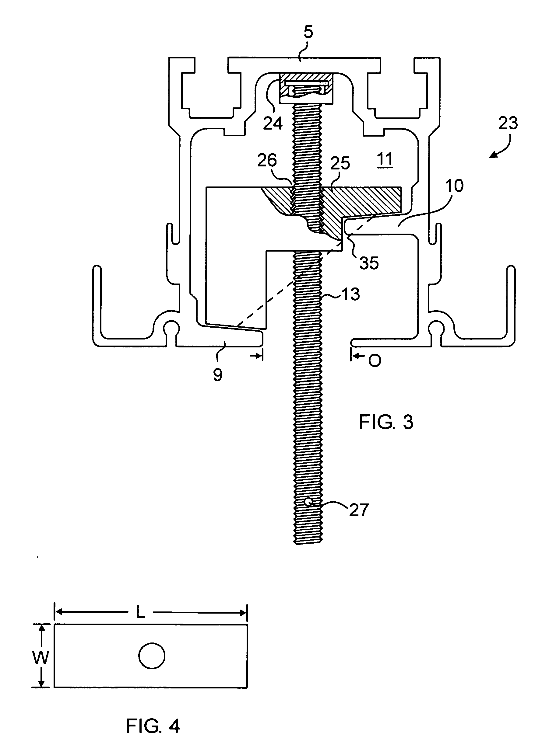
[0016] In a first alternate embodiment of the invention 23 illustrated in FIGS. 3 and 4, the head 24 capping the stem 13 is circular and swivelly attached to it. A lug 25 substantially similar in shape and dimension to the lug 17 used in the first embodiment, has a threaded central bore 26 which is mated to the stem. Again, the overall length L of the lug is substantially greater than the width O of the bottom slot, and its width W is slightly lesser. In other words, the width of the lug is commensurate with the passageway defined between the flanges and rib, and its length is no greater than the width of the internal channel 11 defined by the rail. A diametrical bore 27 in a bottom section of the threaded stem 13 is dimensioned to accept the tip of a screwdriver or other similar tool that can be used to rotate the stem in order to forcefully bring the top of the head 24 against the backplate or top wall 5 of the rail while the lug 25 is forced downwardly against the rib 10 and the ...

embodiment 28

[0017] In a second alternate embodiment 28 of the invention illustrated in FIG. 5, the head 24 capping the threaded stem 13 is similar to the one illustrated in FIG. 3. The lug 29 has a similar central bore 26, but does not have a downward projection. Accordingly, both longitudinal ends 30 of the lug can be brought into contact with the upper surfaces of the flanges 9. The central rib 10 of the previously described embodiments is not used and no longer necessary. The bottom surface 31 of the lug is lined with a resiliently compressible material such as neoprene or nylon in order to increase friction with the flanges.

[0018] The third alternate embodiment 32 of the invention illustrated in FIG. 6, is essentially similar to the second alternate embodiment 28 of FIG. 5, with the addition of a sleeve 33 and nut fastener 34 engaged over the stem under the lug. After the suspension bracket has been secured and immobilized within the rail channel 11 tightening of the nut 34 on the stem 13 p...


PUM


Abstract

A device for suspending equipment such as a lighting fixture of public address speaker from a ceiling mounted track used to suspend a movable partition and including an extruded rail defining a channel having a longitudinal slot opening between flanges or ribs projecting inwardly from opposite walls of the rail. The device comprises a threaded stem capped by an enlarged head passes through the slot opening and is engaged by a lug which cooperates with the head to forcibly bear against or capture one or more of the flanges.

Description

FIELD OF THE INVENTION [0001] This invention relates to track fasteners and more specifically to tracks and slidable attachment brackets used to suspend equipment and structures from ceilings, walls and other similar structural surfaces. BACKGROUND OF THE INVENTION [0002] Arranging a site for spectacle, meeting or other gathering requires the temporary installation of a large amount of equipment and other structures that must be suspended from ceilings, beams or other overhead elements or attached to walls in a very secured, but also quickly adjustable manner. For example, lighting apparatuses for a stage, audio and video equipment, cabling, props and curtain walls for subdividing a large meeting hall are often suspended from rails of tracks affixed to an overhead structure. Bolts passing through holes in the rail or track and appropriate brackets are commonly used, but do not allow quick and easy transversal adjustment of the position of the suspended items along the track. Adjusta...

Claims


Application Information

Patent Timeline
IPC IPC(8): E04H1/00
CPCE04B2/827E04B9/006F21V21/34
Inventor KLEEGE, J. NEVIN
Owner AIRWALL HANGERS
Why Eureka
Try Eureka