Local unit for monitoring the maintenance of an item of equipment and method for the validation of a task on the item of equipment

a technology for monitoring equipment and maintenance, applied in the field of local units for monitoring the maintenance of items of equipment and the validation of tasks on items of equipment, to achieve the effect of reducing the power consumption of the local maintenance monitoring unit and high reliability

Active Publication Date: 2018-07-05
GETRALINE
View PDF22 Cites 8 Cited by
  • Summary
  • Abstract
  • Description
  • Claims
  • Application Information

AI Technical Summary

Benefits of technology

[0030]The data content received by the terminal of the maintenance technician from the short-range display or communication means of the local maintenance monitoring unit constitutes a copy of the check-value and the corresponding timestamp as they result from a latest execution of the renewal sequence. These two values can then be verified, in particular within the portable communication terminal of the maintenance technician, with respect to values that have been transmitted by another channel, in particular via the external server. In this way, the presence of the technician at the location of the equipment is confirmed by the check-value that he recovers on site from the local maintenance monitoring unit. This value must match the latest renewal produced by the random number generator of the local maintenance monitoring unit. Moreover, the encryption of the timestamp that is associated with the check-value, as this encrypted timestamp is transmitted to the terminal of the technician, prevents any attempt to falsify this timestamp for reasons of cheating or criminal intent. The local unit of the invention thus makes it possible to check, with a high level of reliability, that the task performed by the technician on the equipment complies with the terms of his assignment, in particular as regards the identity of the technician and

Problems solved by technology

But under such circumstances, involving a task on assignment at a remote site, the problem arises of verifying that th

Method used


Image

  • Local unit for monitoring the maintenance of an item of equipment and method for the validation of a task on the item of equipment
  • Local unit for monitoring the maintenance of an item of equipment and method for the validation of a task on the item of equipment
  • Local unit for monitoring the maintenance of an item of equipment and method for the validation of a task on the item of equipment

Examples


Embodiment Construction

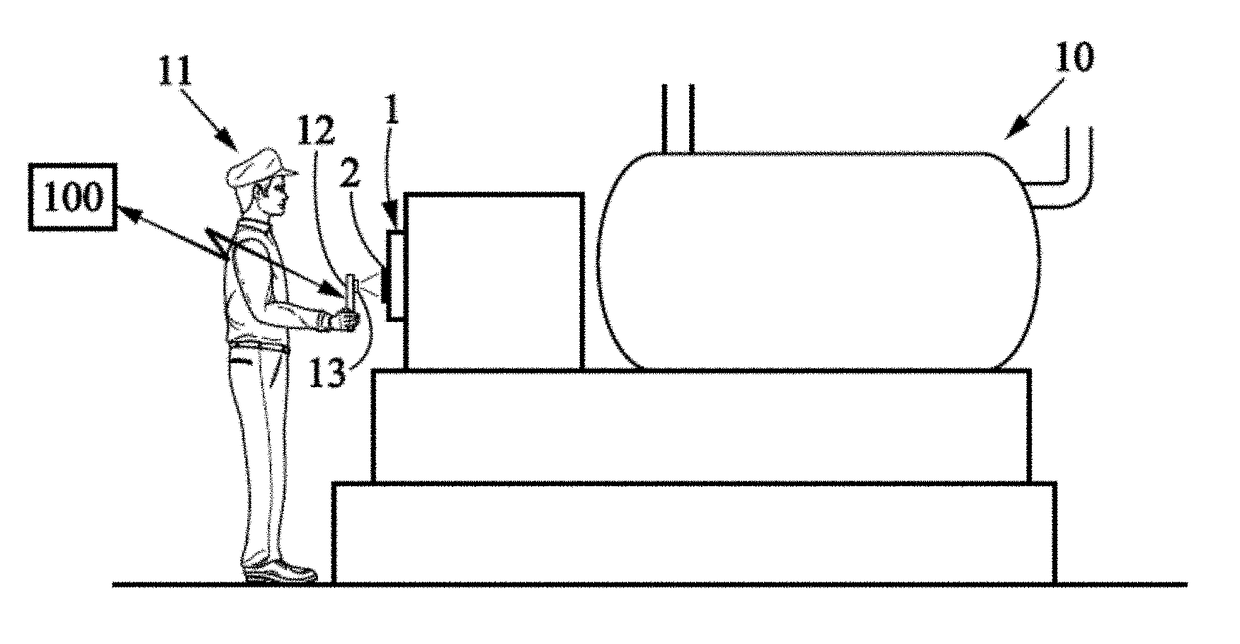
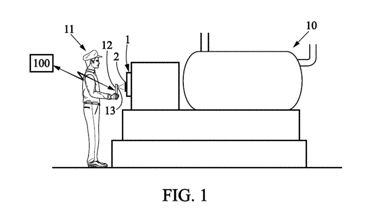
[0068]For sake of clarity, dimensions of the elements shown in FIGS. 1 and 2 do not correspond either to actual dimensions or to actual dimensional ratios. Moreover, identical references that are indicated in different figures denote identical elements or those having identical functions.

[0069]The invention is now described in detail for an item of heating equipment, such as an individual home heating boiler, for example in an apartment of a multiple housing unit. But it is understood that the invention can be applied to any other type of equipment and maintenance task or service, as was indicated at the start of the present description.

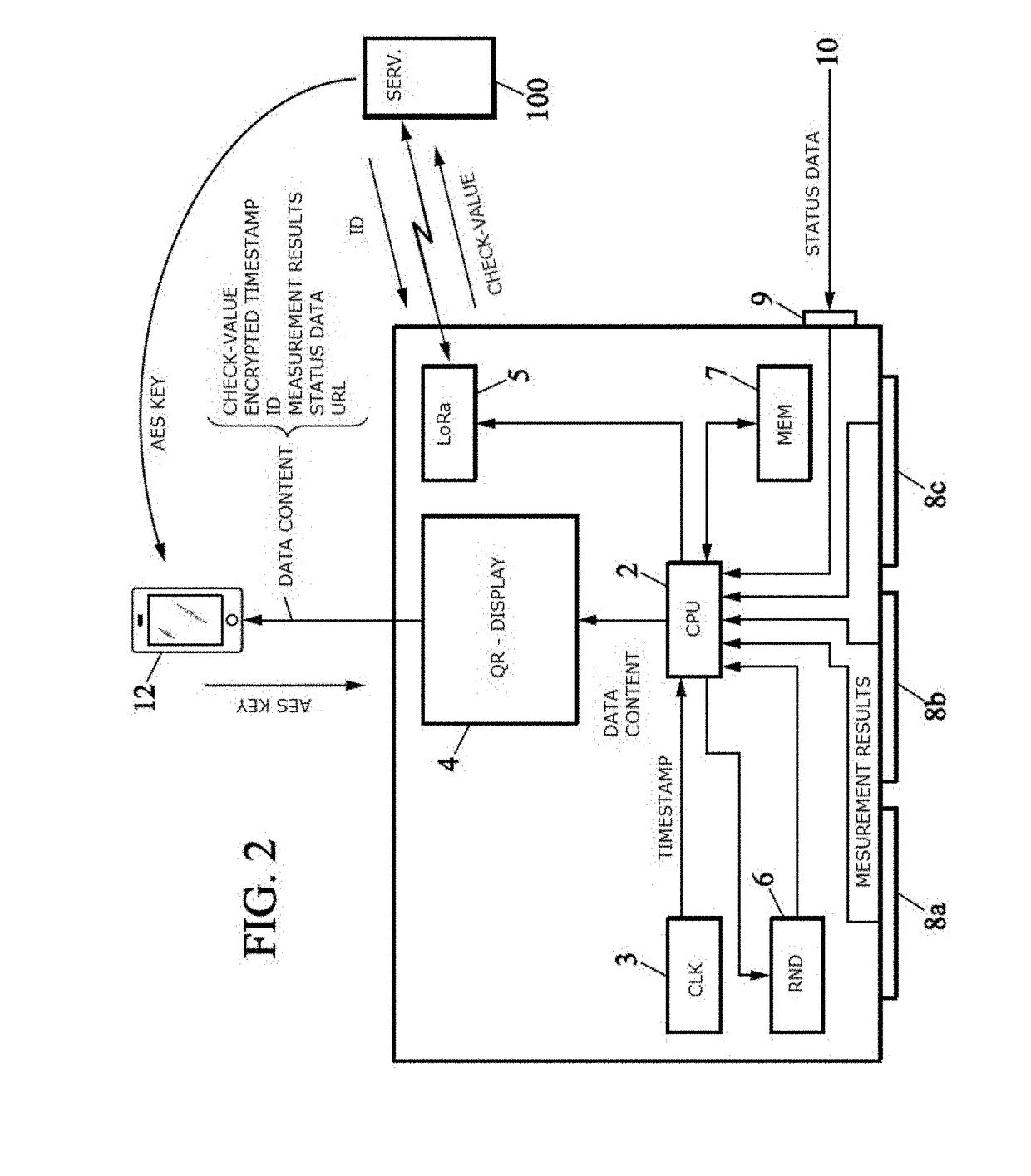
[0070]In the figures, the references indicated have the meanings listed below:[0071]1 local maintenance monitoring unit[0072]2 processor, marked CPU, of the local maintenance monitoring unit[0073]3 clock, marked CLK, of the local maintenance monitoring unit[0074]4 matrix display, marked QR-DISPLAY, of the local maintenance monitoring unit[0075]5 data...


PUM


Abstract

A local maintenance monitoring unit is intended to be installed near an item of equipment, in order to make it possible to validate a task that is carried out by a maintenance technician on the item of equipment. The local maintenance monitoring unit is provided with short-range display or communication unit in order to transmit a check-value and a timestamp to a portable communication terminal with which the technician is equipped. It is thus possible to guarantee that the technician assigned for the task is actually located at the site of the maintenance task.

Description

BACKGROUND OF THE INVENTIONField of the Invention[0001]The present invention relates to a local unit for monitoring the maintenance of an item of equipment, as well as a method for the validation of a task that is carried out on this item of equipment.Description of the Related Art[0002]Many circumstances require a technician to carry out a task on an item of equipment installed at a specified site that is different from the place where a manager of the equipment is located, and may also be different from the workplace where the technician is based. The technician is then sent out on mission to the location of the item of equipment, at an agreed date, in order to carry out the planned maintenance task.[0003]But under such circumstances, involving a task on assignment at a remote site, the problem arises of verifying that the on-site task has actually been performed on the agreed equipment and by the technician to whom the task was assigned. Such verification may be necessary in real...

Claims


Application Information

Patent Timeline
IPC IPC(8): G06Q10/06G06K19/06
CPCG06Q10/063114G06K19/06037H04W4/80G08B25/012G06Q2220/00H04W4/023G08B21/14H04W12/63H04L9/30H04W12/08H04W12/06H04L63/107H04L9/302H04L63/10
Inventor AZPITARTE, JEAN-PATRICKVIOLET, NICOLAS
Owner GETRALINE
Why Eureka
Try Eureka