Motor vehicle lock

a technology for motor vehicles and locks, applied in the field of motor vehicle locks, can solve the problems of high production cost, high precision of all components, and the tendency of worm gear to premature failure, and achieve the effects of low self-locking, simple and economical structur

Active Publication Date: 2011-03-15
BROSE SCHLIESSSYSTEME GMBH & CO KG
View PDF27 Cites 14 Cited by
  • Summary
  • Abstract
  • Description
  • Claims
  • Application Information

AI Technical Summary

Benefits of technology

[0010]The present invention provides a flexible traction means, especially a cable or belt, which can be wound up preferably directly by the motor or the driven shaft of the motor and which acts directly or indirectly on the ratchet. In particular, the ratchet can be opened against a spring force by the traction means. This enables a simple and economical structure, since only a few components and no especially precision-manufactured components are necessary. Another advantage of the present invention resides in the fact that the operating noise of the motor is not transferred by the traction means or is transferred only to a small degree to the other parts. Another advantage resides in the fact that that precision gear engagement, as in a worm gear, is not necessary, so that wear problems in this respect can be avoided. Finally, with the use of the aforementioned traction means for drive engineering purposes, invulnerability to fouling is ensured. Moreover, the greasing which is necessary in toothed gearing is completely eliminated.
[0011]Another advantage of the present invention, is that low self-locking can be accomplished. After the motor is turned off, the traction means can be automatically unwound again by spring force and, thus, the ratchet can be swiveled to be able to move back into its blocking position. Preferably, the reset force is produced by a spring which is present anyway and for example is assigned to the ratchet or a rocker arm or the like which is coupled to the ratchet. In this way, both a simple and thus economical structure and also simple triggering are enabled.
[0012]Preferably, on the ratchet or the assigned rocker arm, there is a deflection roller for the traction means and the free end of the traction means is thrust for example against the housing of the motor vehicle lock. Thus speed transformation is easily achieved, and by the corresponding choice of the geometrical ratios and arrangements a transmission ratio which is adapted to need can be implemented.
[0013]An especially durable arrangement arises by the connection, which has been formed by the traction means, between the motor and the ratchet (a direct connection without an interposed deflection lever). Matching of the speed transformation can be achieved by the fundamentally present possibility of variation of the diameter of the driven shaft.
[0014]Outfitting the ratchet, with an essentially cylindrical section, with the traction means, attached to its jacket surface, leads to an especially compact and economical version. The traction means is then wound and unwound to a certain extent over a certain angle range when the ratchet is moved. The angle range is preferably distinctly less than 180°.
[0015]Other advantages, features, properties and aspects of this invention derive from the following description of preferred embodiments.

Problems solved by technology

This gear requires high precision of all components and therefore high production costs.
In practice, it has been shown that a worm gear tends to premature failure.
Another disadvantage is that a worm gear transfers the motor noise to all other components so that the motor vehicle lock exhibits undesirably high operating noise.

Method used


Image

  • Motor vehicle lock
  • Motor vehicle lock
  • Motor vehicle lock

Examples


Embodiment Construction

[0024]In the figures the same reference numbers are used for the same or similar parts, the corresponding or comparable properties and advantages being achieved even if a repeated description is omitted.

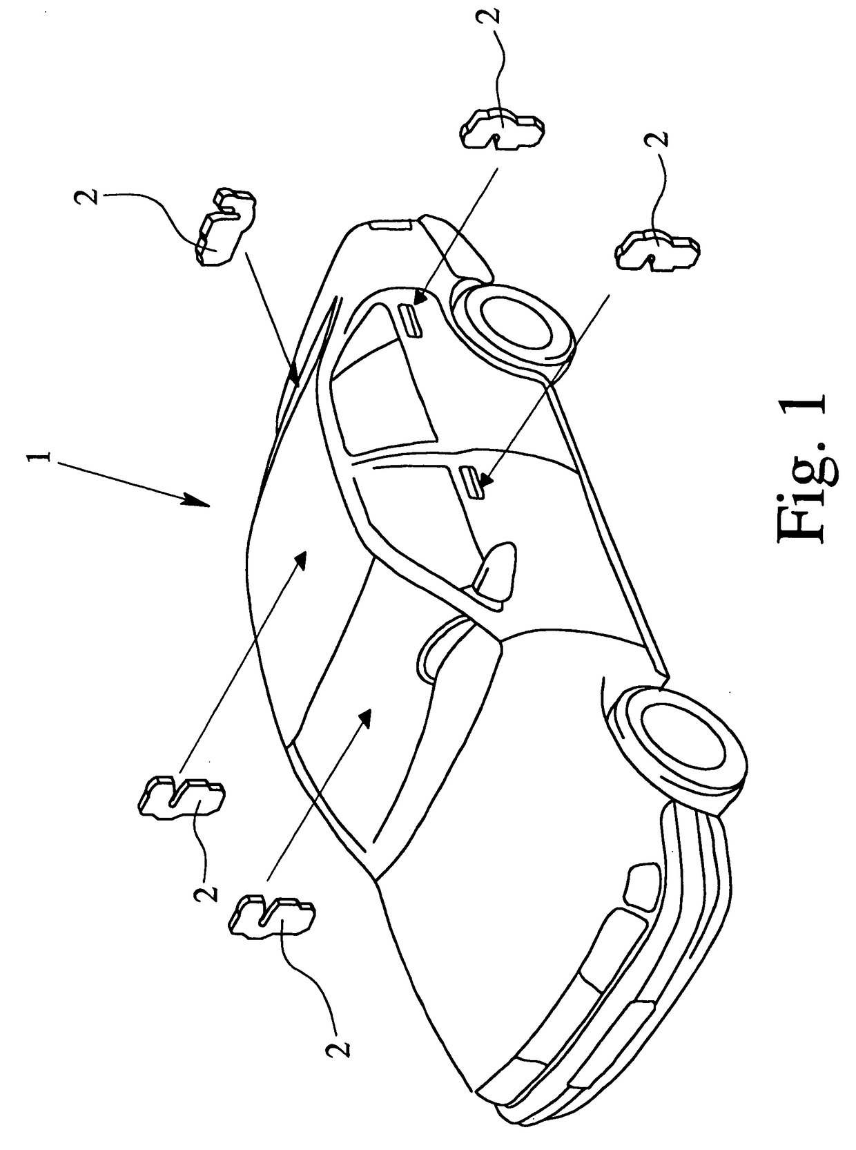
[0025]FIG. 1 schematically shows a motor vehicle 1 with several motor vehicle locks 2, such as side door locks, a hood lock, and the like. The arrows in FIG. 1 indicate the approximate installation position of the illustrated motor vehicle locks 2 in the motor vehicle 1. The term “motor vehicle lock” is defined primarily as the door lock of a motor vehicle. But it can also be a trunk lock, a hood lock, a hatch lock or the like of a motor vehicle. The structure of a motor vehicle lock 2 of the present invention is detailed below.

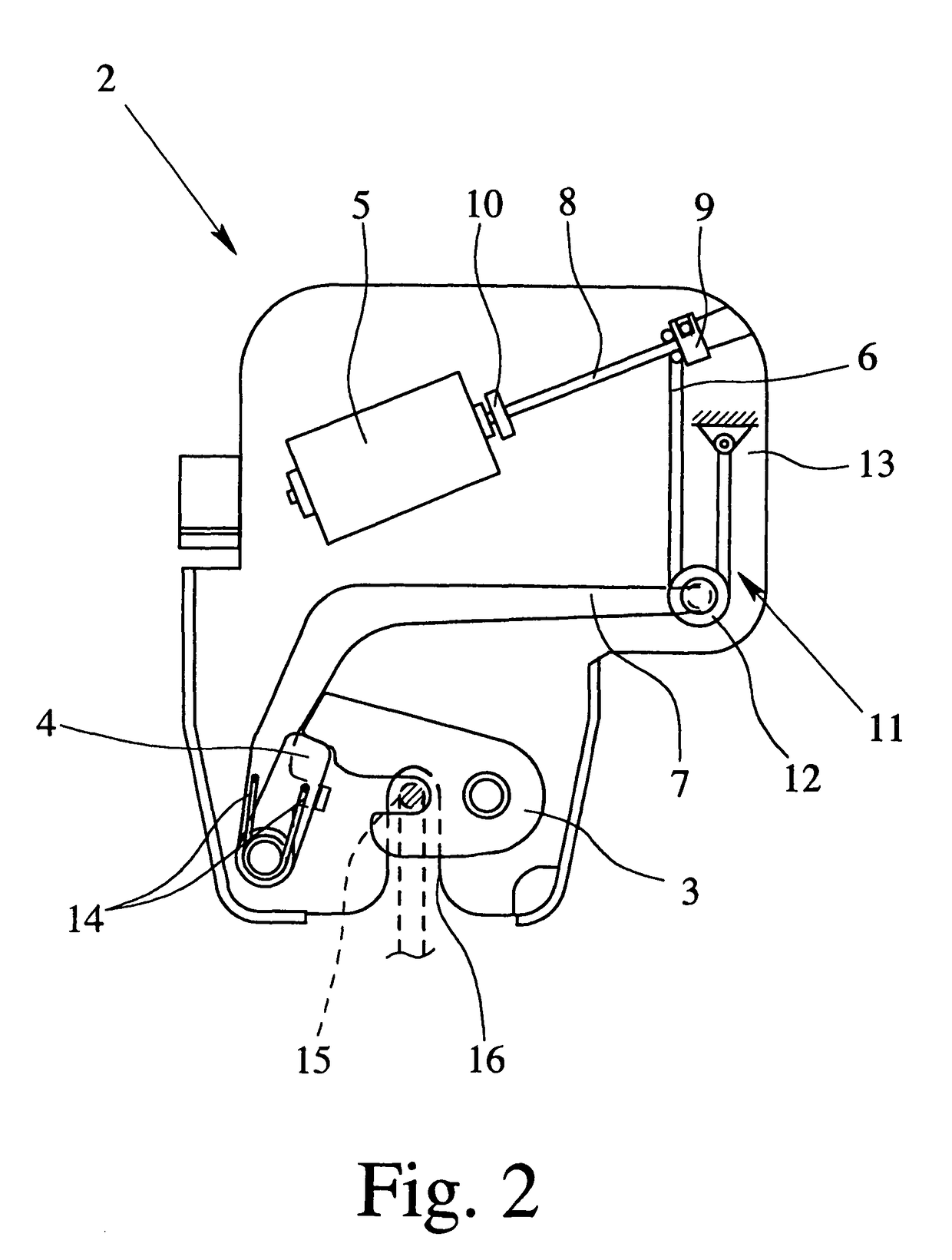
[0026]FIG. 2 schematically shows one exemplary embodiment of a motor vehicle lock 2 shown in a locked state. The motor vehicle lock 2 has a latch 3 which is a rotary latch, an assigned ratchet 4 and a motor 5 for opening the ratchet 4. The ratchet 4 can secure...


PUM


Abstract

A motor vehicle lock with a latch and an associated ratchet and a motor for opening the ratchet. The motor vehicle lock has a flexible traction device which directly or indirectly connects the motor to the ratchet and which is wound up by the motor for opening the ratchet and which can be unwound by spring force when the motor is turned off.

Description

BACKGROUND OF THE INVENTION[0001]1. Field of the Invention[0002]The present invention relates to a motor vehicle lock and, more specifically, to the use of a motor to open the ratchet of a motor vehicle lock.[0003]2. Description of Related Art[0004]A vehicle lock which is known, for example, from published German Patent Application DE 196 14 122 A1, (corresponding to U.S. Pat. No. 5,934,717), and which is popular for motor vehicle side doors, has a latch and an assigned hook-shaped ratchet. The latch can hold or secure a striker and is, for its part, blocked by the ratchet which can engage the latch in a main catch position and a preliminary catch position.[0005]Published German Patent Application DE 20 01 653 A shows a motor vehicle lock with a latch and an assigned (i.e., associated) ratchet. The ratchet is not hook-shaped, but instead made in the manner of a swiveling pin. The pin has a recess that forms an engagement section which can be moved into blocking engagement with the l...

Claims


Application Information

Patent Timeline
Patent Type & Authority Patents(United States)
IPC IPC(8): E05C3/06E05C3/16E05B65/32B60J5/00B62D25/12E05B15/16E05B17/00E05B47/00E05B53/00E05B65/12E05B65/20
CPCE05B17/0004E05B79/20E05B81/14E05B15/1635Y10S292/23Y10T292/1047Y10T292/1082
Inventor STEFANIC, JOSIPKACHOUH, CHECRALLAH
Owner BROSE SCHLIESSSYSTEME GMBH & CO KG
Why Eureka
Try Eureka