Flow straightening apparatus

a flow straightening and apparatus technology, applied in the field of fluid flow mechanics, can solve problems such as unstable flow and irregular flow, and achieve the effects of convenient, economical and universally adapted to resolution, and more economical construction

Active Publication Date: 2010-09-09
MCCROMETER
View PDF17 Cites 21 Cited by
  • Summary
  • Abstract
  • Description
  • Claims
  • Application Information

AI Technical Summary

Benefits of technology

[0012]It is an object of the present invention to provide improved flow straightening apparatus that achieves the advantages of the V-CONE flow straightener and that is of more economical construction and more conveniently, economically and universally adapted to resolution of problematic fluid flow conditions.

Problems solved by technology

A turn, curve or elbow in a pipeline may impart a swirl to the fluid; or a valve or impediment in the conduit through which or around which the fluid is required to flow may distort the flow and cause the flow to become irregular and unstable.

Method used


Image

  • Flow straightening apparatus
  • Flow straightening apparatus
  • Flow straightening apparatus

Examples


Embodiment Construction

[0028]The following is a description of an embodiment of the invention presently contemplated by the inventor to be the best mode of carrying out his invention.

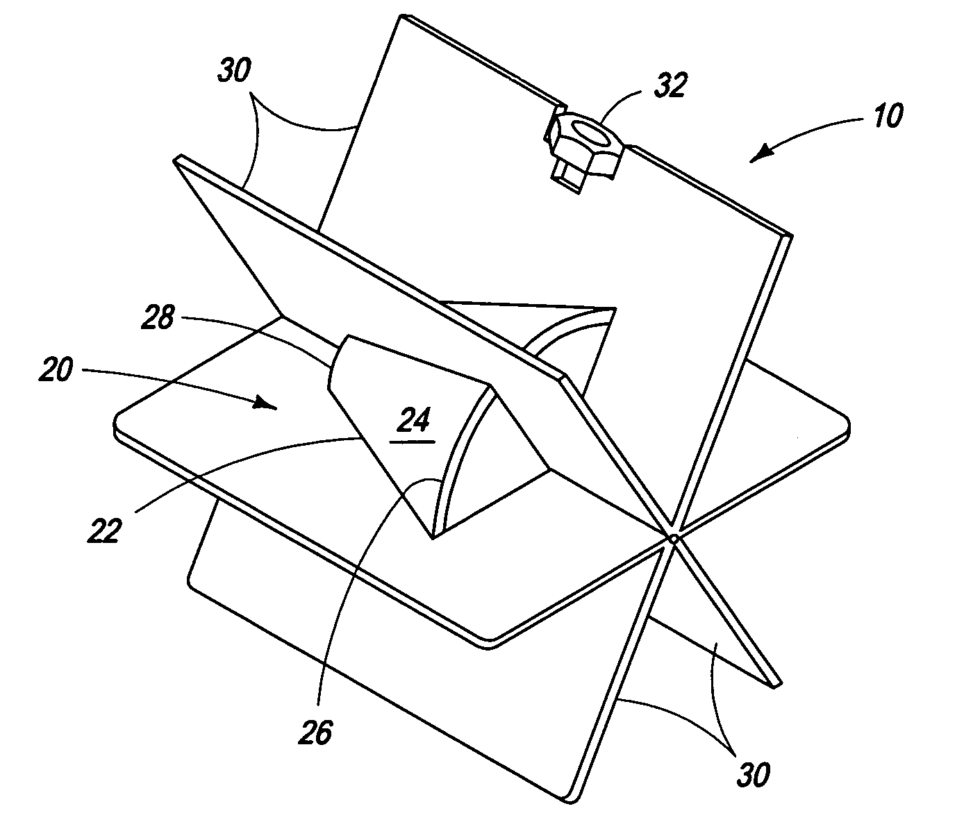
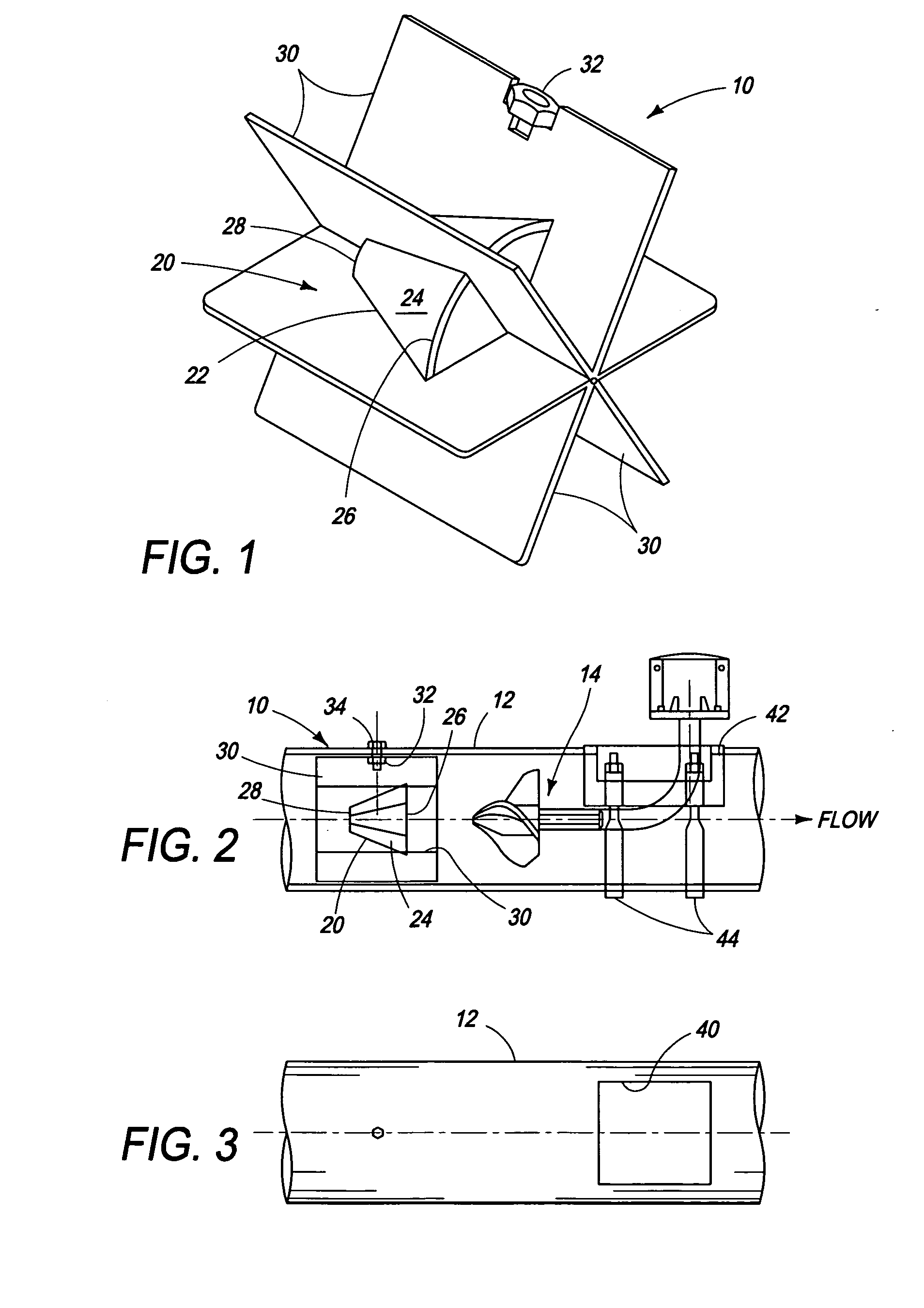
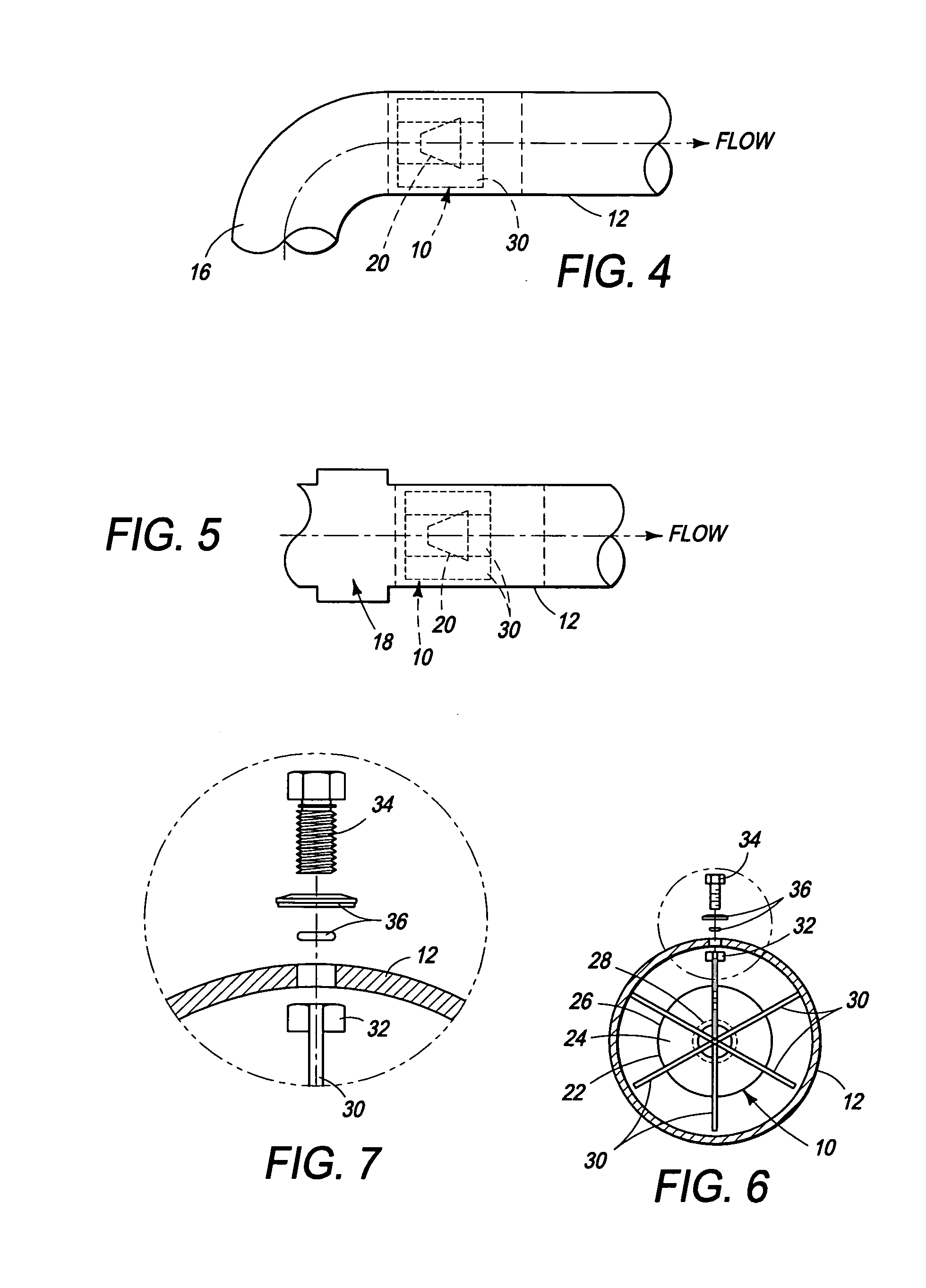
[0029]As shown in FIGS. 2, 4 and 5, the flow straightener of the invention, indicated generally at 10, is adapted to be installed in a pipe or conduit 12, notably an irrigation pipeline 12. The flow straightener 10 is especially adapted for installation upstream from a fluid flow meter 14 as shown in FIG. 2, or downstream from a curve, bend or elbow 16 in the pipeline 12, as shown in FIG. 4, or downstream from a flow disturbing pipe component such as valve 18, as shown in FIG. 5. The valve 18 may for example comprise an irrigation system check valve installed in and comprising part of an irrigation water distribution system pipeline 12.

[0030]In summary, the straightener 10 is adapted to be installed in any new or existing pipeline downstream from any disturbance causing device or upstream from any locale in which it is desire...


PUM


Abstract

An apparatus for straightening fluid flow in a conduit or pipeline, such as an irrigation pipeline, resides in an integral assembly of a conical fluid flow displacement member effective to substantially lineralize the velocity profile of fluid flowing through the pipeline and a plurality of circumferentially spaced vanes extending longitudinally and radially of the conical member and effective to mitigate swirl and eccentric velocity profiles in the flowing fluid. The conical member consists simply of a single cone that is centered in the pipeline by the vanes. A bolt extending through the wall of the pipe and threaded into a nut on a vane secures the straightener in the line.

Description

PRIORITY CLAIM[0001]The present application claims priority to and the benefit of U.S. Provisional Application No. 60 / 930,802 filed on May 18, 2007.FIELD OF THE INVENTION[0002]The present invention relates to fluid flow mechanics, and more particularly, to apparatus, commonly known as flow straighteners, for converting fluid flow in a conduit from unstable and / or distorted conditions to uniform, stable and consistent flow conditions.BACKGROUND OF THE INVENTION[0003]For a variety of reasons, for example, accurate measurement of fluid flow through a conduit or pipeline, such as an irrigation water pipeline, it is desirable that the fluid flowing through the conduit have a substantially flat face velocity profile of maximum mean flow diameter, i.e., a diameter approaching or approximating the inner diameter of the conduit.[0004]Frequently, departures from the optimum occur. The velocity profile maybe become convex or concave, or asymmetrical, or symmetrical but non-uniform, or the flow...

Claims


Application Information

Patent Timeline
Patent Type & Authority Applications(United States)
IPC IPC(8): F15D1/04
CPCG01F15/00F15D1/02
Inventor PINKERTON, ROBERT N.
Owner MCCROMETER
Why Eureka
Try Eureka