Gas distribution assembly with rotary taps for a cooking appliance

a technology of a distribution assembly and a cooking appliance, which is applied in the direction of combustion process, combustion ignition, domestic heating details, etc., can solve the problems of complex structure and economic cost of the assembly, and achieve the effect of simple configuration

Inactive Publication Date: 2006-05-23
COPRECITEC
View PDF3 Cites 48 Cited by
  • Summary
  • Abstract
  • Description
  • Claims
  • Application Information

AI Technical Summary

Benefits of technology

[0005]The gas distribution assembly according to the invention is of simple configuration and economic construction adapted for the installation of an existing type of gas tap, with the mounting base arched. The gas manifold assembly comprises a straight manifold conduit, which has a central part wherein the gas feeder nipple is connected, and two tubular parts on each of which are fitted two oppositely superimposed taps, encircling the tubular part and secured to it by means of common screws.

Problems solved by technology

This known distribution assembly has a structurally complex and economically expensive gas manifold box.

Method used


Image

  • Gas distribution assembly with rotary taps for a cooking appliance
  • Gas distribution assembly with rotary taps for a cooking appliance

Examples


Embodiment Construction

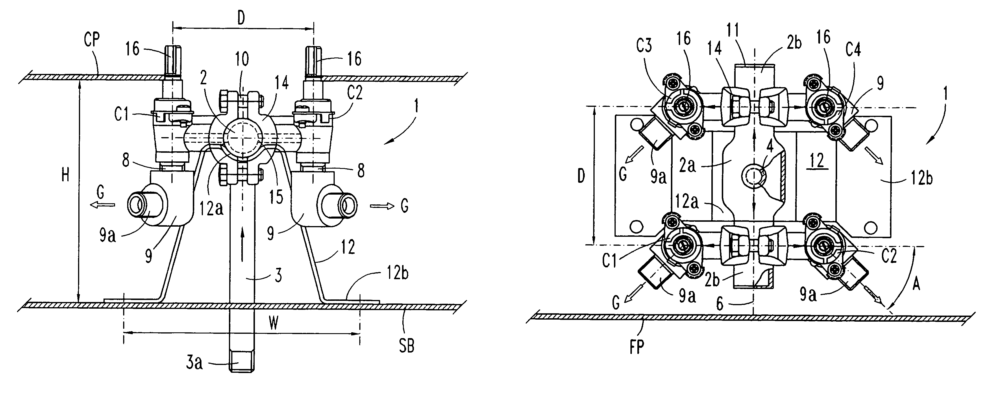
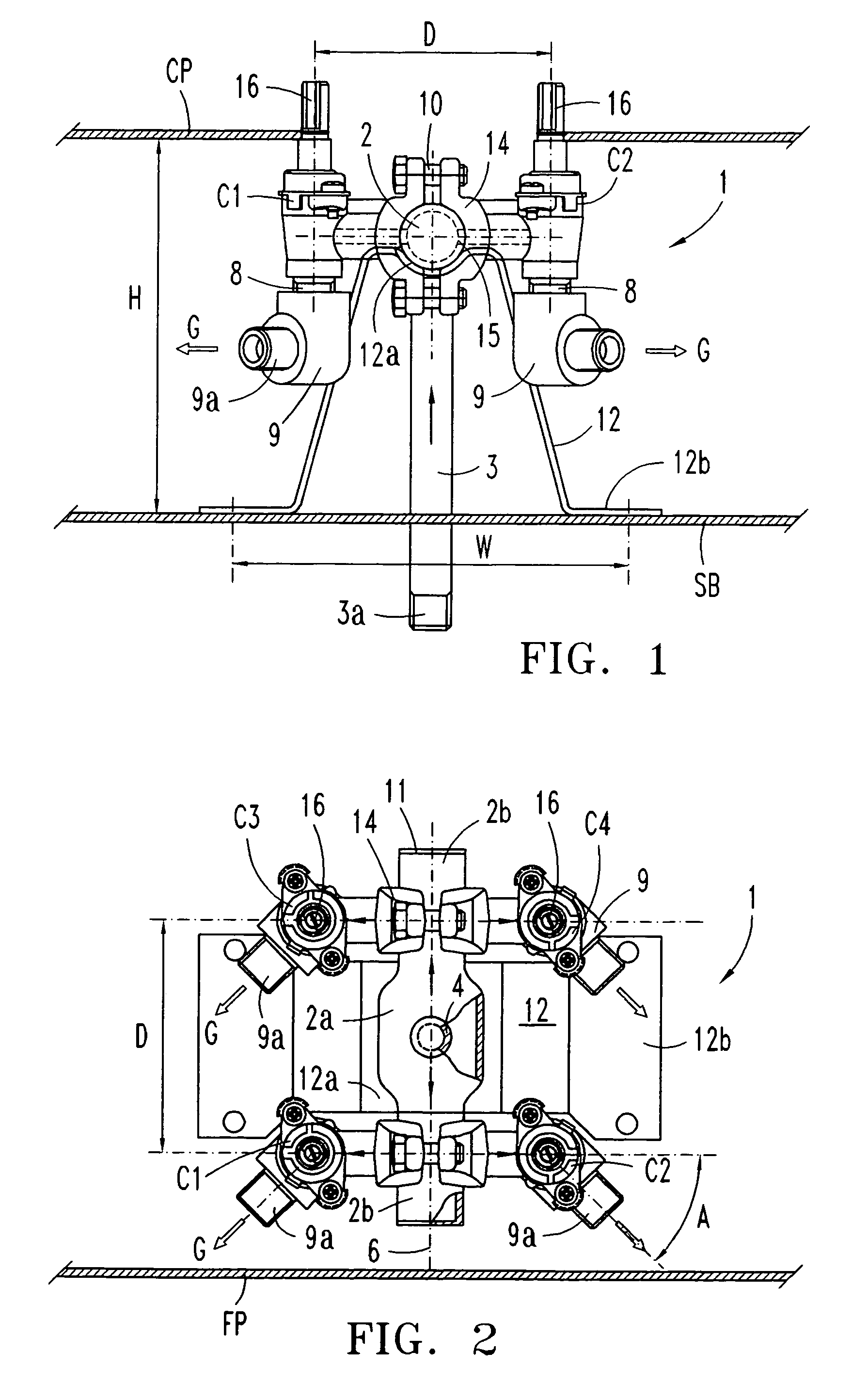
[0009]In reference to FIGS. 1 and 2 a gas distribution assembly embodiment 1 is described as adapted to a cooking appliance with four top burners, comprising a manifold conduit 2 and a gas feeder nipple 3 connected to the manifold conduit, two pairs of taps C1–C4 provided with a tap outlet pipe 8 for the supply of an individual gas flow “G”, a connecting adapter 9 for this tap outlet, and a supporting leg 12 made of folded plate for fixing the manifold assembly 1. The gas distribution assembly is fastened on a horizontal base “SB” of the cooking appliance frame, the manifold conduit 2 being oriented according to an axis 6 at right angles to the front panel “FP” of the appliance, and the tap drive shafts 16 stand out from the horizontal cooking plane “CP” of the appliance in an upward direction, preferably forming a geometric square.

[0010]The manifold conduit 2 has a straight tubular shape, and is formed with a wide central part 2a for connecting the feeder nipple 3, and two narrower...


PUM


Abstract

The gas distribution assembly (1) is adapted for the supply of a gas flow (G) to a cooking appliance with top burners, and comprises a straight tubular-shaped manifold conduit. (2) and various rotary taps (C1–C4) provided with an arched mounting base, which are superimposed in twos opposite to each other on a tubular part (2b) of the manifold, and fixed by means of common screws (10). The tap drive shafts (16) stand out from the horizontal cooking plane (CP) occupying a small-sized square geometric area (D×D) . A supporting leg (12) for the distribution assembly (1) is made of a plate folded and fixed on a horizontal structural base (SB), the gas feeder nipple (3) being connected to a central hollow part (2a) of the manifold, extended in a direction opposite to that of the drive shafts (16).

Description

TECHNICAL FIELD OF THE INVENTION[0001]The present description relates to the supply of gas to a household cooking appliance provided with various top burners by way of a gas flow distribution assembly fitted with a number of rotary type regulating taps mounted on a manifold conduit, and to a constructional detail for the installation of the manifold assembly on an appliance wall.PRIOR ART[0002]Fuel gas distribution assemblies fitted with manual rotary type taps are already well known. They are installed on a panel of the cooking appliance frame with the tap drive shafts aligned on the front panel of the appliance or forming a square projecting above the horizontal cooking plane. The gas manifold assembly disclosed for instance in GB-2182429-A comprises a main round section distribution pipe or common rail on which a number of manual rotary taps are fitted in line. The manifold pipe or gas rail has its two ends sealed with plugs and each tap takes the gas flow from an individual hole...

Claims


Application Information

Patent Timeline
Patent Type & Authority Patents(United States)
IPC IPC(8): F23Q9/08F23K5/00F23Q9/00F24C3/00
CPCF24C3/12
Inventor ALBIZURI, INIGO
Owner COPRECITEC
Why Eureka
Try Eureka