Sealing apparatus and sealing method using the sealing apparatus

a sealing apparatus and sealing technology, applied in the field of sealing apparatus, can solve the problems of reducing the vibrational energy applied to the workpiece, the relative velocity of the workpiece and the anvil against the ultrasonic horn is extremely high, and the sealing failure tends to occur in the workpiece, etc., to achieve sufficient sealing energy and high processing speed

Active Publication Date: 2005-07-07
UNI CHARM CORP
View PDF14 Cites 46 Cited by
  • Summary
  • Abstract
  • Description
  • Claims
  • Application Information

AI Technical Summary

Benefits of technology

[0009] The present invention has been worked out in view of the shortcomings in the prior art set forth above. It is therefore an object of the present invention to provide a sealing apparatus wherein a relative velocity of a second holding member (e.g., ultrason

Problems solved by technology

Accordingly, since the ultrasonic vibration from the ultrasonic horn cannot be applied sufficiently long to areas of the workpiece to be sealed, sealing failure tends to occur in the workpiece.
Such sealing failure due to a decrease in vibrational energy applied to th

Method used


Image

  • Sealing apparatus and sealing method using the sealing apparatus
  • Sealing apparatus and sealing method using the sealing apparatus
  • Sealing apparatus and sealing method using the sealing apparatus

Examples


Embodiment Construction

[0036] The present invention will be discussed hereinafter in detail in terms of the preferred embodiment according to the present invention with reference to the accompanying drawings. In the following description, numerous specific details are set forth in order to provide a thorough understanding of the present invention. It will be obvious, however, to those skilled in the art that the present invention may be practiced without these specific details. In other instance, well-known structures are not shown in detail in order to avoid unnecessary obscurity of the present invention.

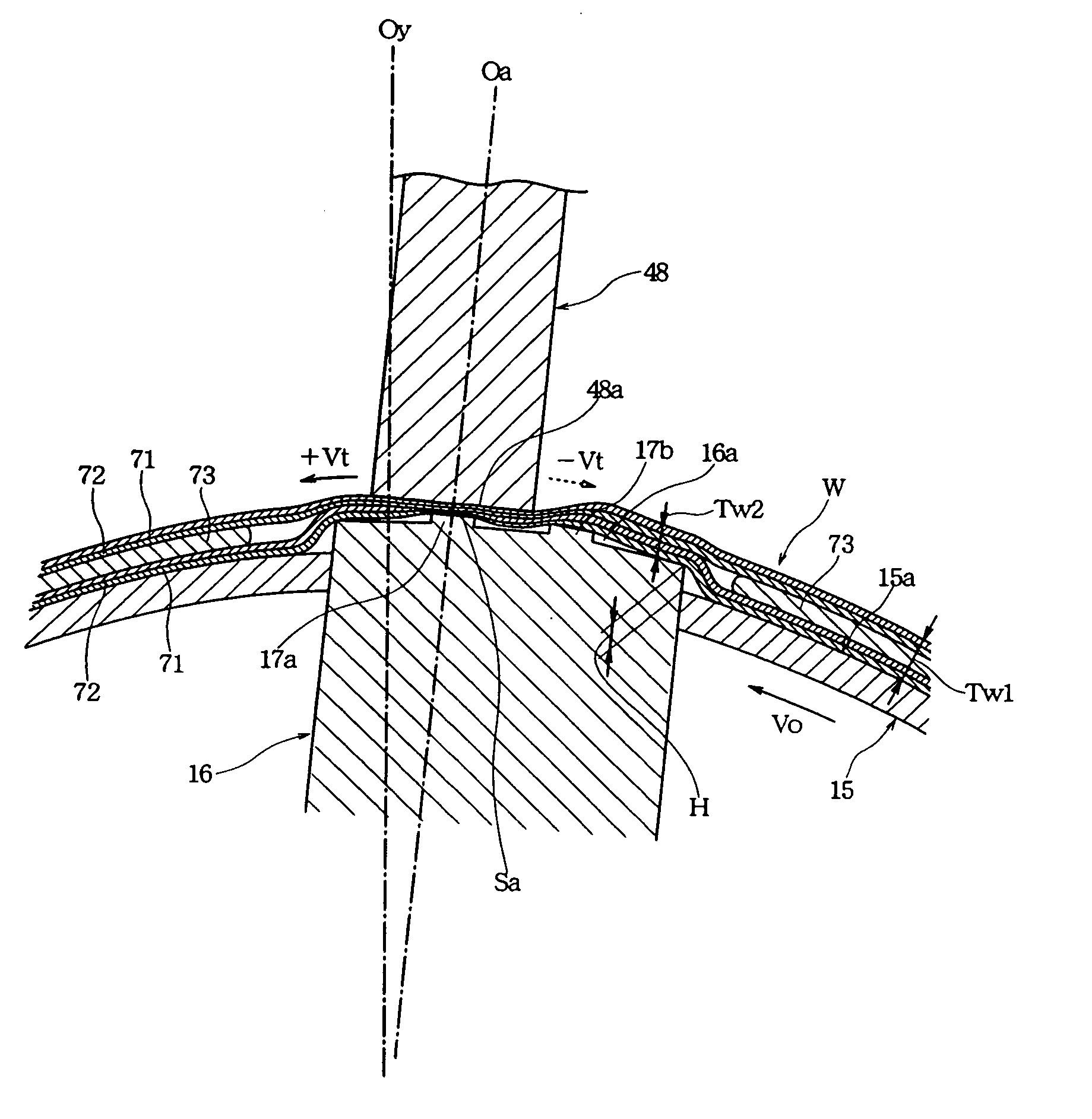
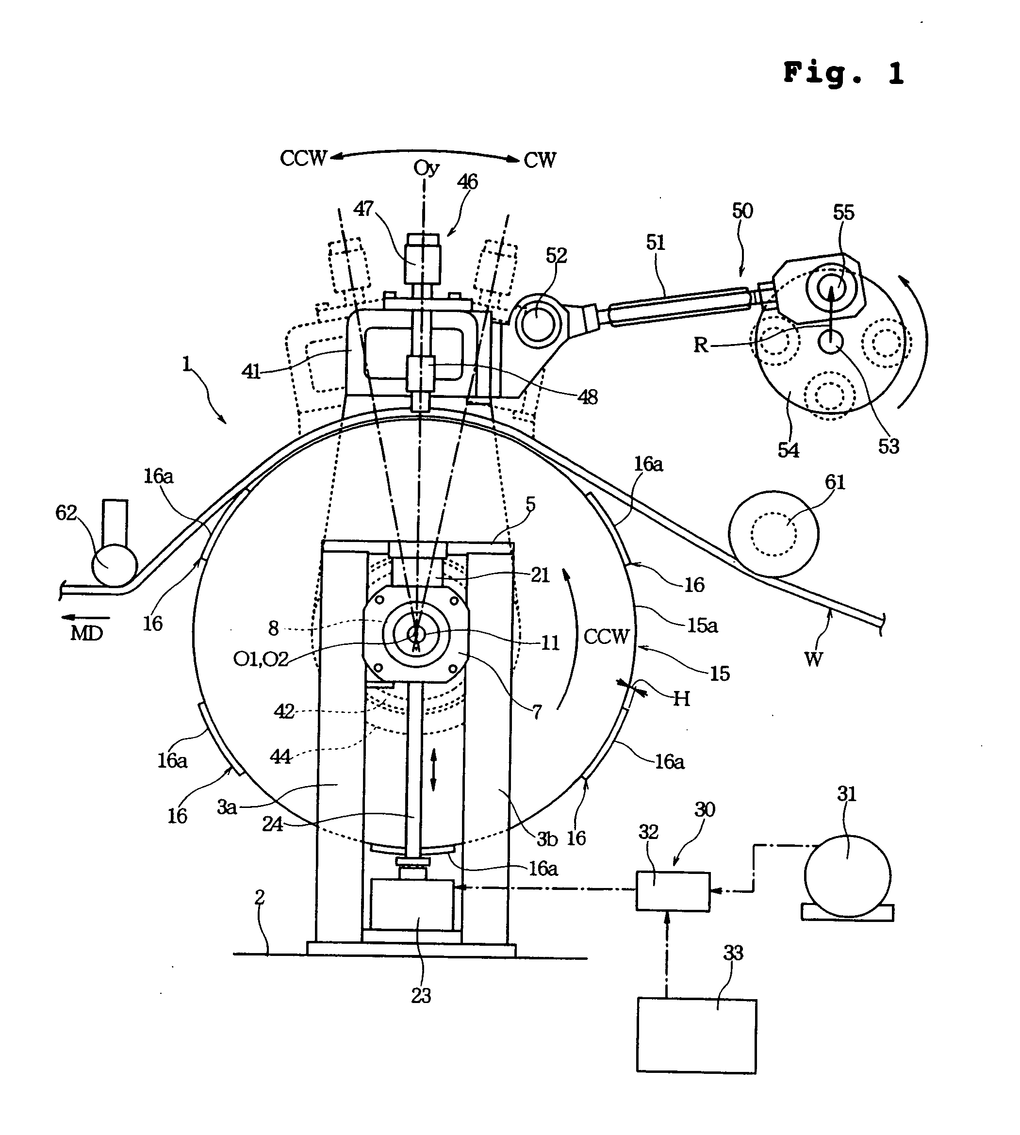
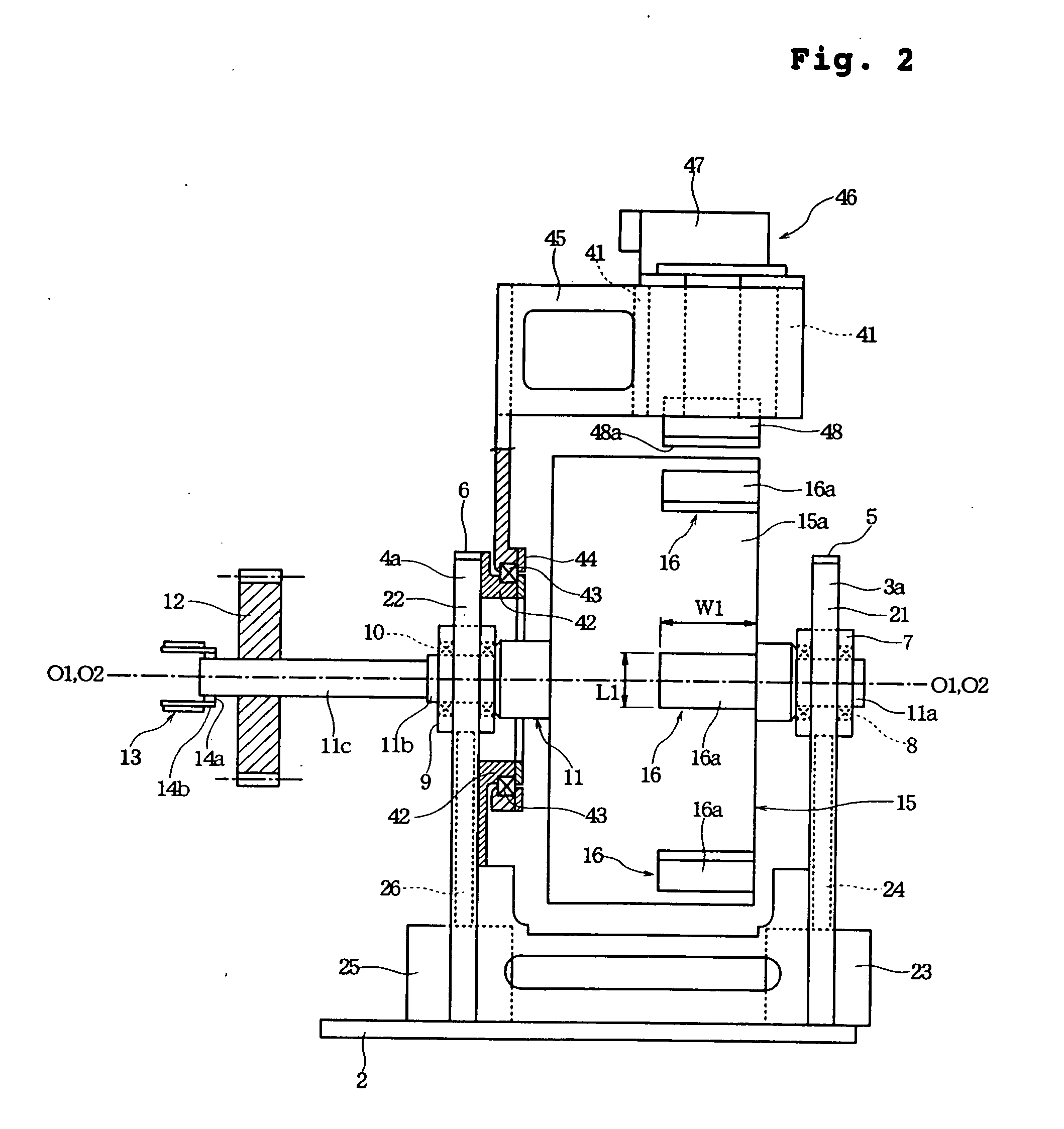
[0037]FIG. 1 is a front view of a sealing apparatus according to one embodiment of the present invention; FIG. 2 is a left side view of the sealing apparatus; FIG. 3 is an explanatory diagram illustrating operation of the sealing apparatus; FIG. 4 is an enlarged sectional view showing one example of sealing operation; FIG. 5 is a perspective view showing a state where an anvil as first holding member an...


PUM

PropertyMeasurementUnit
Pressureaaaaaaaaaa
Velocityaaaaaaaaaa

Abstract

Disclosed is a sealing apparatus including an anvil of a sealing abutment surface, which is driven to circulate with a constant peripheral velocity, and an ultrasonic horn of a sealing abutment surface, which is driven to reciprocate with varying velocities. Since the relative velocity of a soft workpiece moving along with the anvil against the sealing abutment surface of the ultrasonic horn can be made low, a sealing energy from the ultrasonic horn may be applied to the soft workpiece sufficiently long.

Description

BACKGROUND OF THE INVENTION [0001] 1. Field of the Invention [0002] The present invention relates to a sealing apparatus for sealing (or welding) two or more sheets, such as thermoplastic films, thermoplastic nonwoven fabrics or a combination thereof, and a sealing method using the sealing apparatus, more particularly, relates to a sealing apparatus suitable for use in manufacturing an article having a seal, such as disposable diaper or sanitary napkin, and a sealing method using the sealing apparatus. [0003] 2. Description of the Related Art [0004] Sealing apparatuses which can seal a stack of two or more sheets such as thermoplastic resin films or nonwoven fabrics comprising thermoplastic fibers by fusing the films or fibers are disclosed, for example, in Japanese Unexamined Patent Publication No. H05-15551 (Patent Publication 1) and Japanese Examined Patent Publication No. H02-43631 (Patent Publication 2). As disclosed in the Patent Publication 1, such a sealing apparatus may be ...

Claims


Application Information

Patent Timeline
IPC IPC(8): A61F13/00A61F13/15A61F13/496A61F13/49B29C65/00B29C65/08
CPCA61F13/15739B29C66/93431B29C66/8242B29C66/83411B29C66/83415B29C66/83511B29C66/83541B29C66/93441B29L2031/4878B29C65/086B29C66/932B29C66/9241B29C66/1122B29C66/4312B29C66/43129B29C66/81427B29C66/961B29C66/7294B29C66/81433B29C66/91231B29C66/91421B29C66/91431B29C66/91641B29C66/93451B29C65/00B29C65/18B29C65/305B29C65/72B29C66/21B29C66/431B29C66/433B29C66/73921B29C66/232B29C66/81435B29C66/8226B29C66/72343
Inventor YAMAMOTO, HIROKI
Owner UNI CHARM CORP
Why Eureka
Try Eureka