Laser shock hardening method and apparatus

Active Publication Date: 2007-11-15
KK TOSHIBA
View PDF26 Cites 42 Cited by
  • Summary
  • Abstract
  • Description
  • Claims
  • Application Information

AI Technical Summary

Benefits of technology

[0036] By providing a solid transparent to the wavelength of an irradiating laser at a distance from the surface of a workpiece and filling the light path of the laser between the solid and the surface of the workpiece with a liquid, according to the present invention, the liquid has no free surface in the light path of the laser. In principle, therefore, there is no possibility of sputtering of the liquid and waving of the liquid surface upon laser irradiation. It thus becomes possible to stably irradiate a predetermined point with a laser beam and to increase the processing speed by using a laser oscillator with a higher repetition.
[0037] By filling the light path of an irradiating laser from the laser exit of a laser irradiation device to the surface of a workpiece with a liquid transparent to the wavelength of the laser, according to the present invention, the liquid has no free surface in the light path of the laser. In principle, therefore, there is no possibility of sputtering of the liquid and waving of the liquid surface upon laser irradiation. It thus becomes possible to stably irradiate a predetermined point with a laser beam and to increase the processing speed by using a laser oscillator with a higher repetition.
[0038] By providing a liquid jet nozzle at the laser exit of a laser irradiation device and jetting a liquid transparent to the wavelength of an irradiating laser coaxially with a laser beam so as to fill the light path of the laser from the laser exit to the surface of a workpiece with the liquid, according to the present invention, the liquid has no free surface in the light path of the laser. Accordingly, it becomes possible to stably irradiate a predetermined p

Problems solved by technology

Laser irradiation, on the other hand, enables precise and high-speed control of energy density and irradiation point and can carry out high-speed processing, rapid heating/quenching processing, etc. which are difficult with other methods.
Upon irradiation with a laser beam, there occurs the phenomenon that a high-pressure plasma, generated on the surface of the material, spatters the liquid and disturbs the liq

Method used


Image

  • Laser shock hardening method and apparatus
  • Laser shock hardening method and apparatus
  • Laser shock hardening method and apparatus

Examples


first embodiment

[0060]FIG. 4 is an explanatory diagram illustrating a laser shock hardening method according to a first embodiment of the present invention. The same members or elements as those of FIG. 1 are designated with the same reference numerals, and a duplicate description thereof will be omitted.

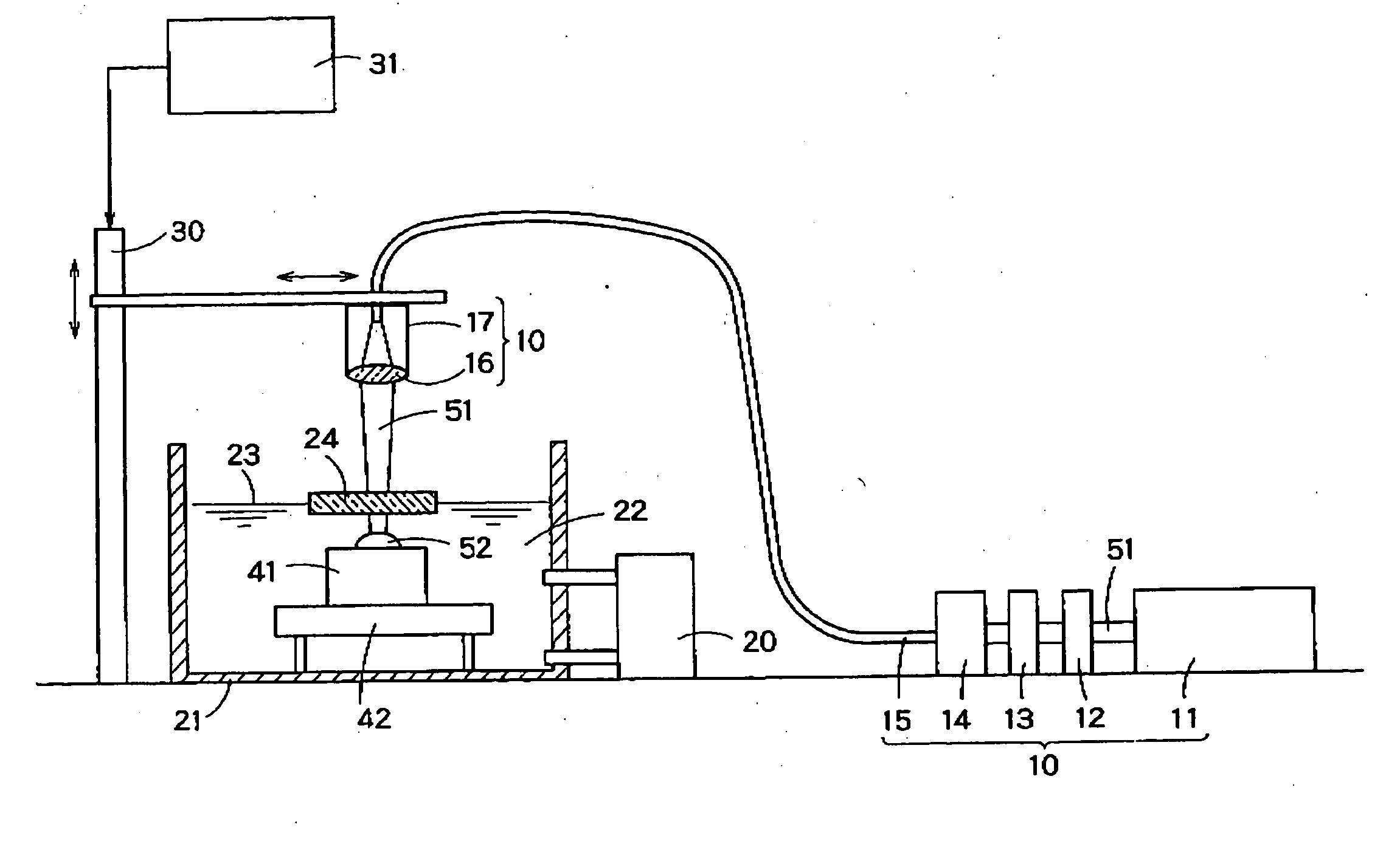
[0061] A workpiece 41 is set on a holder 42 placed in a liquid 22 filled in a vessel 21. The holder 42, which fixes the workpiece 41, has a position adjustment function of adjusting the height, angle, etc. of the workpiece 42.

[0062] A pulsed laser beam 51, emitted from a laser oscillator 11, passes through a power adjustment device 12, a shutter 13 and an optical injection system 14 and enters an optical fiber 15. The laser beam 51 emerging from the optical fiber 15 is directed by an irradiation head 17 having a lens 16 toward the workpiece 41 in the liquid 22. While moving the irradiation head 17 along the surface of the workpiece 41 by means of a driving device 30, the laser beam 51 is intermit...

second embodiment

[0075]FIG. 5 is an explanatory diagram illustrating a laser shock hardening method and apparatus according to a second embodiment of the present invention. The same members or elements as those of the first embodiment are designated with the same reference numerals and a duplicate description thereof will be omitted.

[0076] The workpiece 41 in this embodiment is, unlike that of the first embodiment, a structure which cannot be placed in the liquid in the vessel 21 in carrying out laser shock hardening, for example, a bridge pier.

[0077] In the case where the workpiece 41 is a bridge pier, the laser beam 51 emitted from the irradiation head 17 is applied to a heat-affected zone around a weld zone 43 to adjust the material characteristics including residual stress.

[0078] To obtain the desired effect of laser shock hardening, the irradiation portion 44 needs to be covered with the liquid22 when it is irradiated with the laser beam 51. However, in the case where the irradiation portion...

third embodiment

[0085]FIGS. 6 through 11 are explanatory diagrams illustrating a laser shock hardening method according to a third embodiment of the present inventions. The apparatus shown in FIG. 4 can be used for the laser shock hardening method of this embodiment. Thus, the same members or elements as those of the first embodiment are designated with the same reference numerals and a duplicate description thereof will be omitted.

[0086] The characteristic feature of the third embodiment of the present invention resides in the velocity of relative movement between a laser beam and a workpiece. The moving velocity of the laser beam is related to how the laser spot moves on the surface of the workpiece. FIG. 6 shows a distribution of irradiation spots 45 on the surface of the workpiece 41 in laser shock hardening as carried out by the conventional technique. FIG. 7 is a diagram illustrating an irradiation interval between adjacent irradiation spots 45. While moving the irradiation head 17 at a pred...


PUM

PropertyMeasurementUnit
Sizeaaaaaaaaaa
Frequencyaaaaaaaaaa
Areaaaaaaaaaaa

Abstract

There is provided an improved laser shock hardening method and apparatus which can eliminate spattering of a liquid and waving of the liquid surface upon laser irradiation, and can stably irradiate a workpiece with a laser beam. Thus, the present invention provides in a laser shock hardening method for carrying out surface processing of a workpiece in contact with a liquid by irradiating through the liquid the surface of the workpiece with a pulsed laser beam intermittently emitted from a laser irradiation device, the improvement comprising: providing a solid transparent to the wavelength of the laser, serving as an entrance window to the surface of the liquid; allowing the liquid to be present in the light path of the laser beam between the solid and the surface of the workpiece; and allowing the laser beam to enter through the solid and irradiating through the liquid the surface of the workpiece with the laser beam, thereby shock-hardening the surface of the workpiece.

Description

BACKGROUND OF THE INVENTION [0001] 1. Field of the Invention [0002] The present invention relates to a laser shock hardening method and apparatus for irradiating the surface of a solid material, such as a metal or a ceramic, with a pulsed laser beam through a liquid to adjust surface or internal characteristics of the material, such as structure, hardness and residual stress. [0003] 2. Background Art [0004] Defects In a structure, such as corrosion and cracks, in most cases originate from the surface, and the life of the structure depends on its surface characteristics. Attempts have therefore been made to improve the mechanical or chemical properties of the surface of a material, such as fatigue strength, corrosion resistance and wear resistance, thereby prolonging the life of the structure. [0005] Shot peening is a typical surface processing technique. This technique enables a rise in the hardness of a surface layer of a workpiece and introduction of compressive residual stress in...

Claims


Application Information

Patent Timeline
IPC IPC(8): B23K26/00
CPCB23K26/0066B23K26/063B23K26/067B23K26/0676B23K26/0876B23K26/00B23K26/121B23K2203/04B23K26/0069B23K26/0009B23K26/0045B23K26/106B23K26/0006B23K26/0622B23K26/1224B23K2103/05B23K2103/50B23K2103/52B23K26/356B23K26/352B23K2103/04
Inventor SANO, YUJIMUKAI, NARUHIKOYODA, MASAKIONO, YOSHIAKISAEKI, RYOICHINAITO, HIDEKI
Owner KK TOSHIBA
Why Eureka
Try Eureka