
A kind of electric spindle and machine tool

An electric spindle and shaft core technology, which is applied in the fields of turning and boring, can solve the problems of high cost, poor bearing rigidity, and inability to adjust the preload force of the electric spindle bearing, so as to achieve the effect of high processing speed and good rigidity.

Active Publication Date: 2022-04-29
GUANGZHOU HAOZHI ELECTROMECHANICAL
View PDF9 Cites 0 Cited by
  • Summary
  • Abstract
  • Description
  • Claims
  • Application Information

AI Technical Summary

Problems solved by technology

[0002] The electric spindle is one of the most important core components of the CNC machine tool. The existing electric spindle has the following disadvantages: 1. The preload of the electric spindle bearing is not adjustable, and the rigidity of the bearing is not good at high speed; 2. The electric spindle needs to cooperate Peripheral equipment such as chillers and cutting fluids are cooled, and the occupied area and related costs of the peripheral equipment are relatively high; 3. The existing electric spindle cannot realize the function of spraying coolant when the spindle is running, and the cost is relatively high

Method used


Image

  • A kind of electric spindle and machine tool
  • A kind of electric spindle and machine tool

Examples


Embodiment Construction

[0027] This part will describe the specific embodiment of the present invention in detail, and the preferred embodiment of the present invention is shown in the accompanying drawings. Each technical feature and overall technical solution of the invention, but it should not be understood as a limitation on the protection scope of the present invention.

[0028] In the present invention, if there is a description of directions (up, down, left, right, front and back), it is only for the convenience of describing the technical solution of the present invention, rather than indicating or implying that the referred technical features must have specific Orientation, construction and operation in a particular orientation, therefore should not be construed as limiting the invention.

[0029] In the description of the present invention, if "first" and "second" are used only for the purpose of distinguishing technical features, it should not be understood as indicating or implying relati...


PUM


Abstract

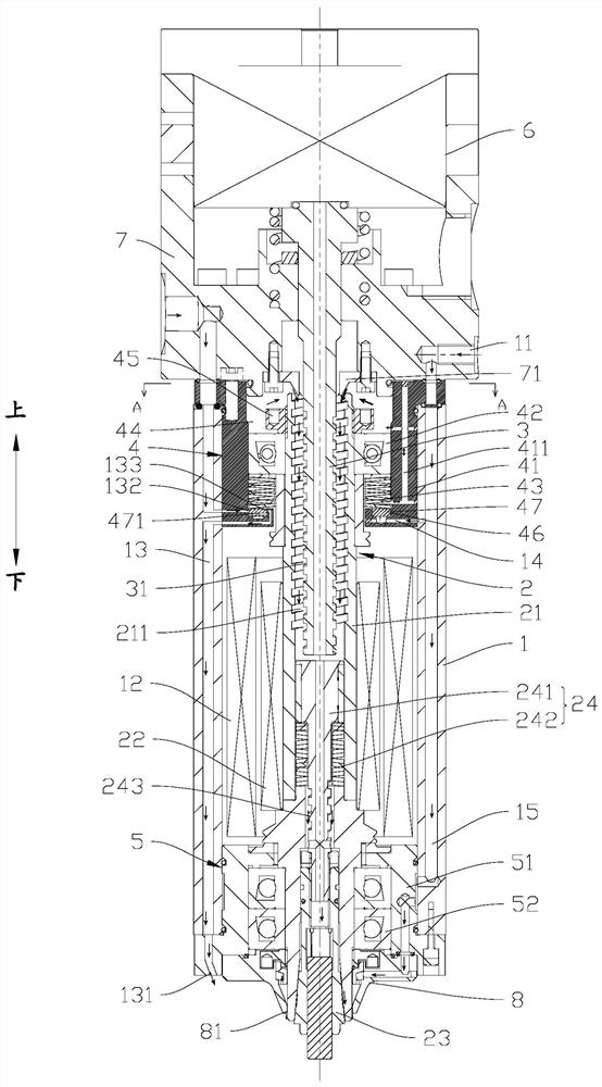
The invention discloses an electric spindle and a machine tool, comprising: a machine body assembly provided with an air inlet and a stator; a shaft core assembly supported on the machine body assembly through an upper bearing assembly and a lower bearing assembly, and the shaft core assembly includes a shaft core, a rotor, The pull rod assembly and collet; the push rod, which extends from the upper end of the shaft core into the inner hole of the shaft core; wherein, the upper bearing assembly includes an upper bearing seat, an upper bearing and a bearing preloading part, and the upper bearing seat defines a closed inner cavity, The inner hole of the shaft core communicates with the inner cavity. The upper bearing and the bearing preloading part are arranged in the inner cavity. The bearing preloading part is supported between the upper bearing and the upper bearing seat. There is a floating part in the piston chamber, and the floating part is in contact with the bearing preloading part. The inner hole of the shaft core and / or the pull rod assembly and / or the push rod are provided with a helical structure, so that after the shaft core assembly rotates, the inner cavity The air is exhausted through the inner hole of the shaft core. The invention realizes that the higher the machining speed of the spindle, the better the rigidity.

Description

technical field [0001] The invention is used in the fields of turning and boring, and in particular relates to an electric spindle and a machine tool. Background technique [0002] The electric spindle is one of the most important core components of the CNC machine tool. The existing electric spindle has the following disadvantages: 1. The preload of the electric spindle bearing is not adjustable, and the rigidity of the bearing is not good at high speed; 2. The electric spindle needs to cooperate Peripheral equipment such as chillers and cutting fluid are cooled, and the area occupied by the peripheral equipment and related costs are relatively high; 3. The existing electric spindle cannot realize the function of spraying coolant when the spindle is running, and the cost is relatively high. Contents of the invention [0003] The purpose of the present invention is to solve at least one of the technical problems in the prior art, and provide an electric spindle and a machi...

Claims


Application Information

Patent Timeline
Patent Type & Authority Patents(China)
IPC IPC(8): B23B19/02B23Q3/12B23Q11/10
CPCB23Q1/70B23Q3/12B23Q11/10
Inventor 张翰乾伍曦张伟江黄孙可程振涛汤秀清
Owner GUANGZHOU HAOZHI ELECTROMECHANICAL
Learn More