
Loop Control System and Method

a control system and loop technology, applied in the field of loop control systems and methods, can solve the problem that additional memory may not be readily available at a wireless computing devi

Inactive Publication Date: 2009-12-31
QUALCOMM INC
View PDF25 Cites 46 Cited by
  • Summary
  • Abstract
  • Description
  • Claims
  • Application Information

AI Technical Summary

Benefits of technology

[0008]One particular advantage provided by at least one of the disclosed embodiments is reduced code size, lower power operation, and higher speed processing of instructions that are executed as pipelined software loops. Other aspects, advantages, and features of the present disclosure will become apparent after review of the entire application, including the following sections: Brief Description of the Drawings, Detailed Description, and the Claims.

Problems solved by technology

Such additional memory may not be readily available at a wireless computing device.

Method used


Image

  • Loop Control System and Method
  • Loop Control System and Method
  • Loop Control System and Method

Examples


Embodiment Construction

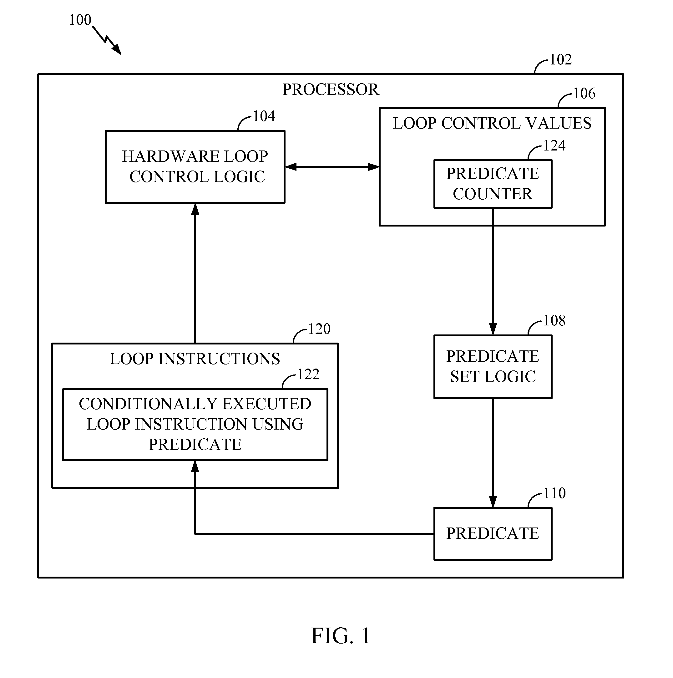
[0015]Referring to FIG. 1, a first illustrative embodiment of a loop control system is depicted and generally designated 100. The system 100 may be part of computer, a portable wireless device, a wireless telephone, or any other device that executes software instructions. The system 100 includes a processor 102 with a hardware loop control logic circuit 104.

[0016]The processor 102 is configured to execute loop instructions 120. The loop instructions 120 include at least one conditionally executed loop instruction 122 that uses a predicate logic circuit 110. For example, the conditionally executed loop instruction 122 may be executed by the processor 102 when the predicate logic circuit 110 stores a predicate value evaluating to true, and the conditionally executed loop instruction 122 may not be executed when the predicate logic circuit 110 stores a predicate value evaluating to false. Executing the loop instructions 120 enables the processor 102 to efficiently perform repeated oper...


PUM


Abstract

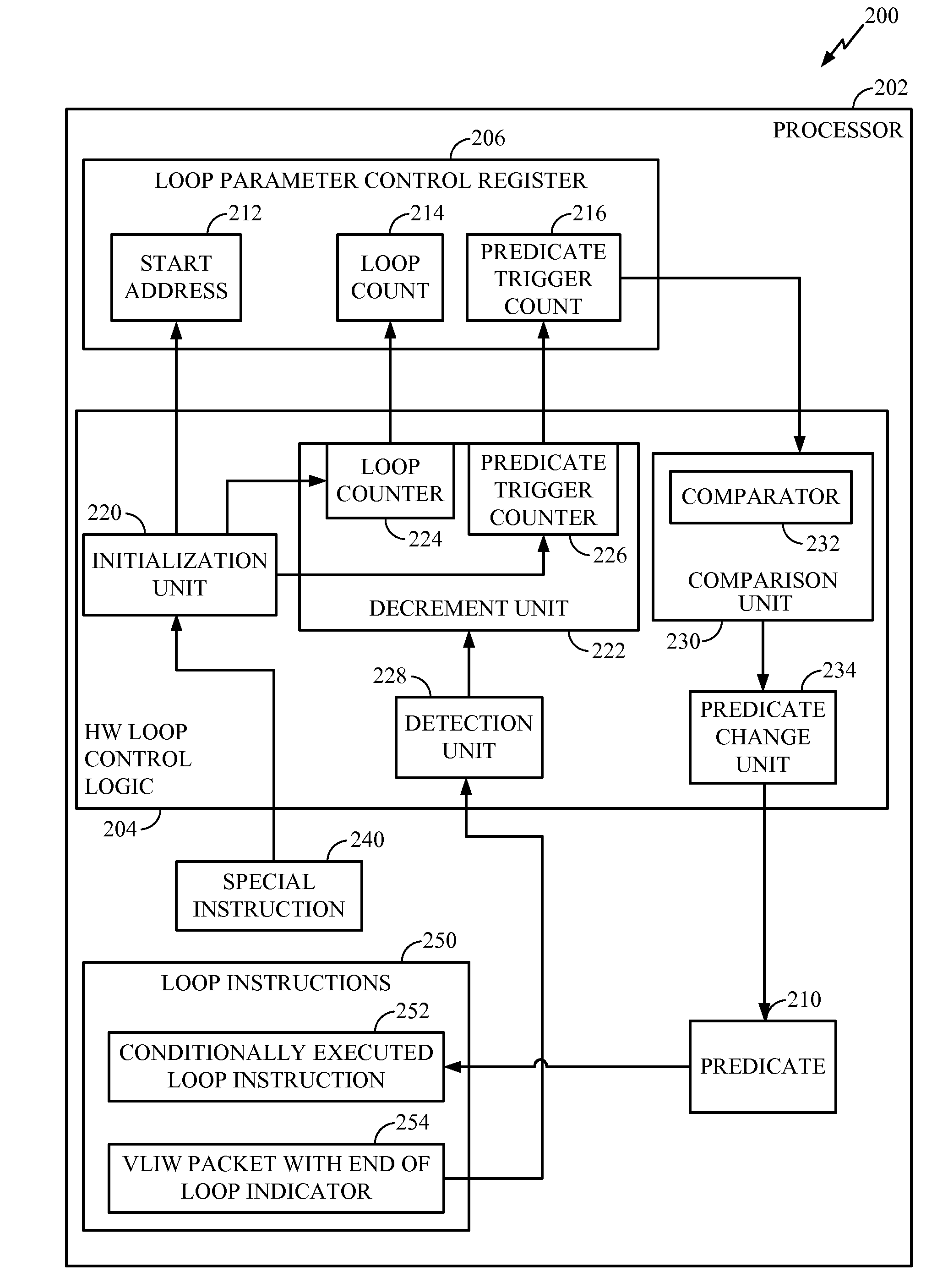
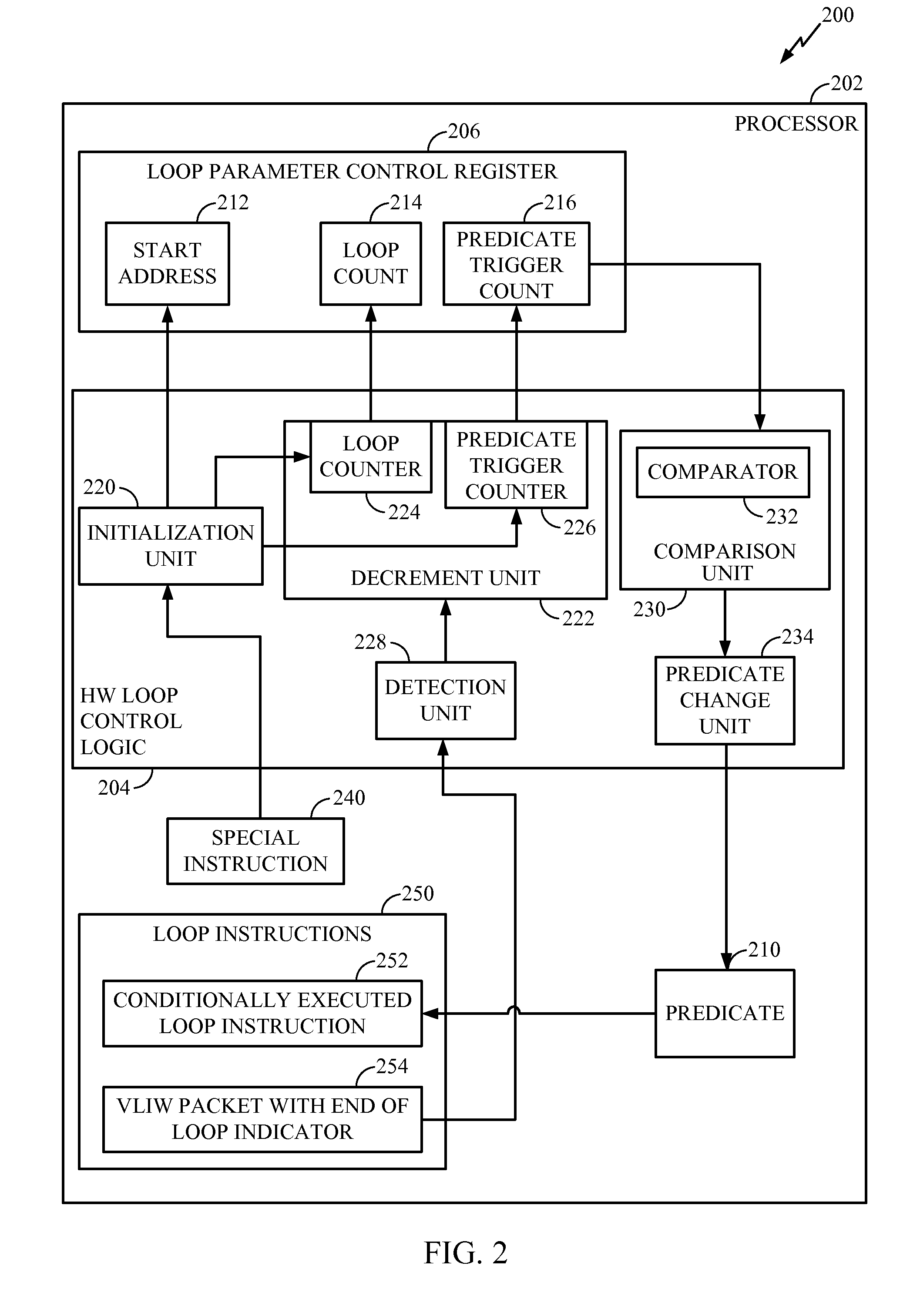
Loop control systems and methods are disclosed. In a particular embodiment, a hardware loop control logic circuit includes a detection unit to detect an end of loop indicator of a program loop. The hardware loop control logic circuit also includes a decrement unit to decrement a loop count and to decrement a predicate trigger counter. The hardware loop control logic circuit further includes a comparison unit to compare the predicate trigger counter to a reference to determine when to set a predicate value.

Description

I. FIELD[0001]The present disclosure is generally related to loop control systems and methods.II. DESCRIPTION OF RELATED ART[0002]Advances in technology have resulted in smaller and more powerful computing devices. For example, there currently exist a variety of portable personal computing devices, including wireless computing devices, such as portable wireless telephones, personal digital assistants (PDAs), and paging devices that are small, lightweight, and easily carried by users. More specifically, portable computing devices, such as cellular telephones and IP telephones, can communicate voice and data packets over wireless networks. Further, many such portable wireless devices also incorporate other types of devices. For example, a wireless telephone can also include a digital still camera, a digital video camera, a digital recorder, and an audio file player. Also, such wireless telephones can process executable instructions, including software applications, such as a web brows...

Claims


Application Information

Patent Timeline
IPC IPC(8): G06F9/30
CPCG06F8/4452G06F9/30072G06F9/3885G06F9/3853G06F9/325G06F8/54
Inventor CODRESCU, LUCIANPLONDKE, ERICH JAMESWANG, LINVENKUMAHANTI, SURESH K.
Owner QUALCOMM INC
Learn More