Laser processing apparatus and laser processing method

a laser processing and laser processing technology, applied in the field of laser processing technology, can solve the problems of limiting the number of points branched toward, requiring a long processing time, and achieving no appreciable effect, and achieves high processing speed, enhanced positional accuracy at the time of application, and easy selection of conditions.

Inactive Publication Date: 2005-06-02
SEIKO EPSON CORP
View PDF37 Cites 55 Cited by
  • Summary
  • Abstract
  • Description
  • Claims
  • Application Information

AI Technical Summary

Benefits of technology

[0020] where P is a pitch between the plurality of beams, M is a number of branches of the beam, and L is an amount of shifts (in the above formula, S is a natural number, and L is a multiple of a natural number of P). In this way, it is made possible to easily select conditions for obtaining the desired number of shots.
[0021] The relative shift of the above-mentioned plurality of beams may be performed intermittently. It is possible to enhance the positional accuracy at the time of applying a beam by stopping when applying a beam and shifting after irradiation.
[0022] Relative shifting between the plurality of beams and the target may be at consecutively variable speed, or motion at fixed speed. By making consecutive shifts without stopping the shift, high speed processing can be made. Further, by shifting at a variable speed, it becomes possible to enhance irradiation accuracy at the time of applying a beam, and further, when a complete stop is made, there is a possibility of positional slippage due to inertia. However, with the consecutive shifts, there is no such positional slippage. Still further, in the conventional method of using a plurality of laser generators, it is difficult to adjust and maintain a pitch accuracy among the beams in this case, so that irradiation while making consecutive shifts was difficult. However, according to the present invention, since one laser generator is used, it is possible to irradiate while making consecutive shifts.
[0023] It is preferable to arrange the above-mentioned plurality of beams in a matrix manner. Since a great number of spot traces may be formed all at once according to this method, further efficiency and high speed processing of numerous holes may be made.
[0024] It is preferable for the above-mentioned plurality of beams to scan back and forth on a scanning line that has once been scanned. According to this, processing with certainty becomes possible, thus making it possible to supply processed products of stable quality.

Problems solved by technology

However, in such a method, since processing is performed to each point, in a case where there are a great number of points to be processed, shifting and stopping (acceleration and reduction of speed) of the target is repeated per point to be processed, an enormous period of time is required for processing.
Yet, there is a limit to the number of points branched toward due to an output limit of the laser generator.
Hence, in the case of a substantial number of points to be processed, no appreciable effect is obtained.
Nevertheless, when using a plurality of laser generators in this manner, it is difficult to carry out adjustments to correct slippage of optical axes of the laser generators.
In this case, it is difficult to carry out adjustments and maintenance of pitch accuracy among the beams.
Still further, use of a plurality of laser generators increases equipment cost, thus leading to a rise in the processing cost of a product.
On the other hand, in the case of using the photolithographic process through mask projection, the time for processing is long and cost is high, hence, it is not suitable for processing large-sized substrates.

Method used


Image

  • Laser processing apparatus and laser processing method
  • Laser processing apparatus and laser processing method
  • Laser processing apparatus and laser processing method

Examples


Embodiment Construction

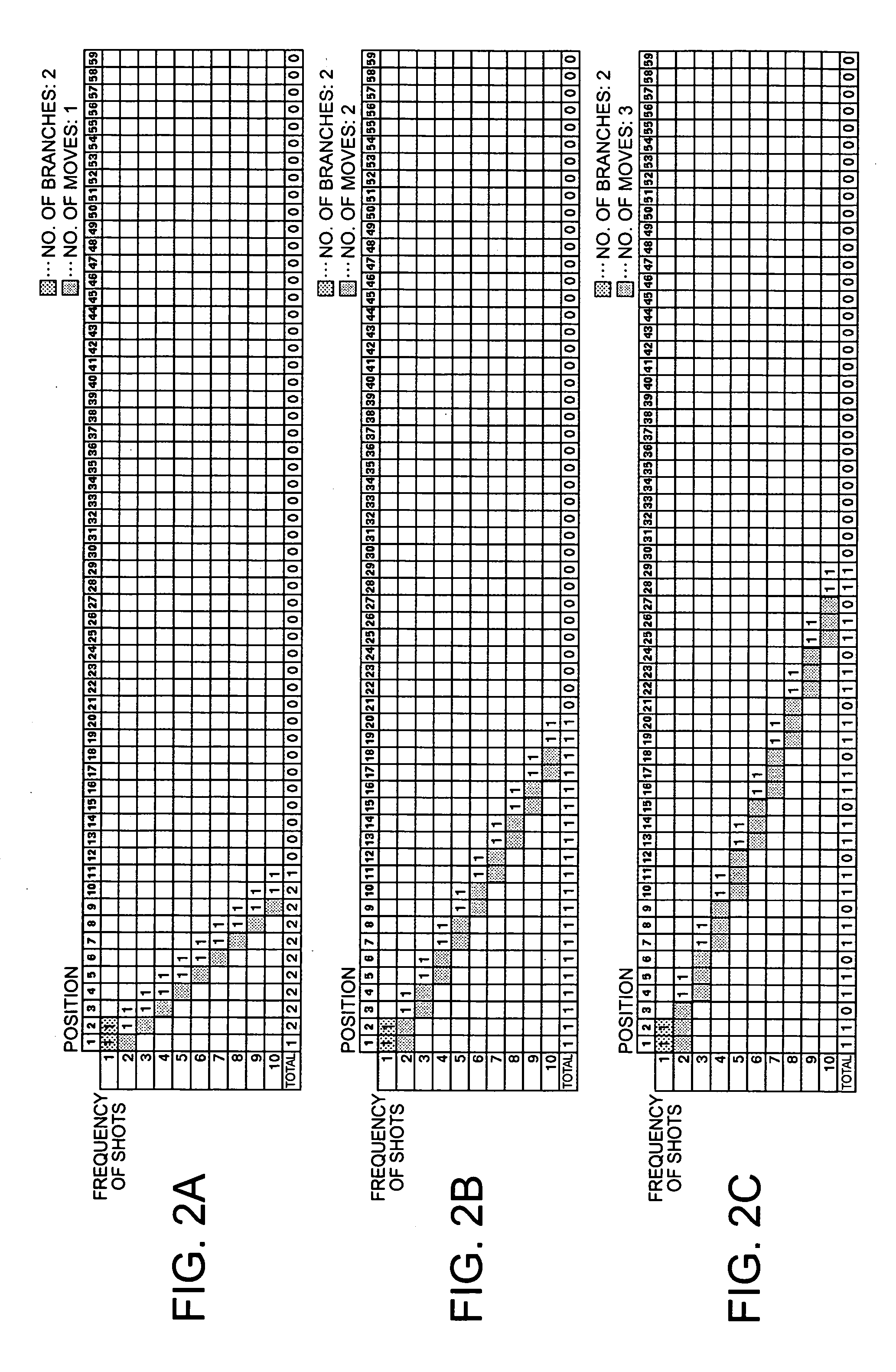
[0032] An embodiment of the present invention will be described as follows with reference to the drawings. In an embodiment of the present invention, a light beam generated from one laser generator is branched out to a plurality of beams arranged at equal intervals.

[0033] A group of spot traces is formed on a target with these branched beams, and irradiation is performed by shifting the plurality of beams to be applied subsequently such that the preceding group of spot traces overlaps part of the spots. This enables a multiplicity of spot traces to be efficiently mass produced without being restricted by the output of the laser generator.

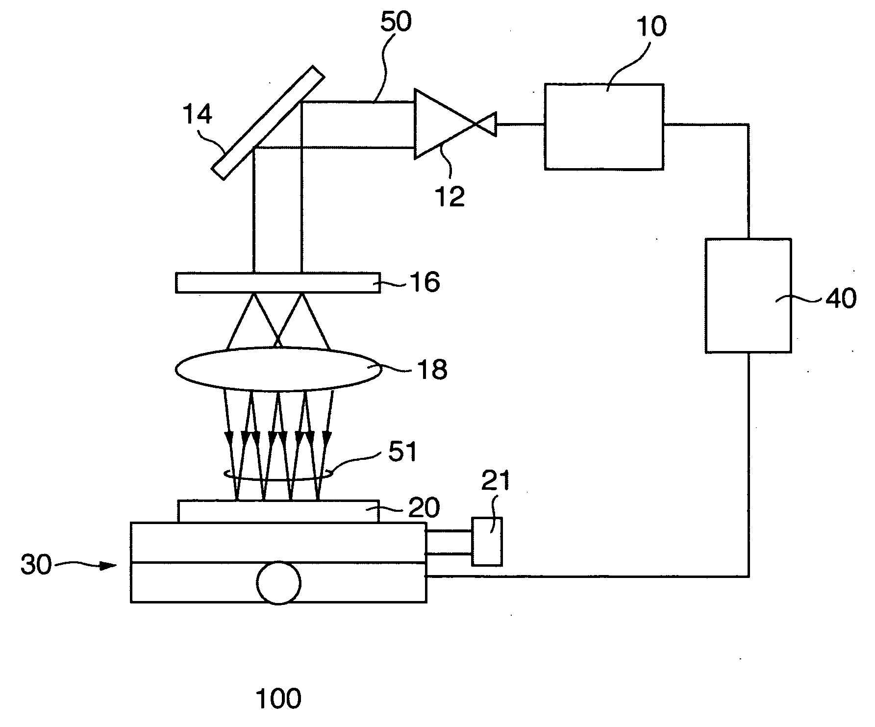
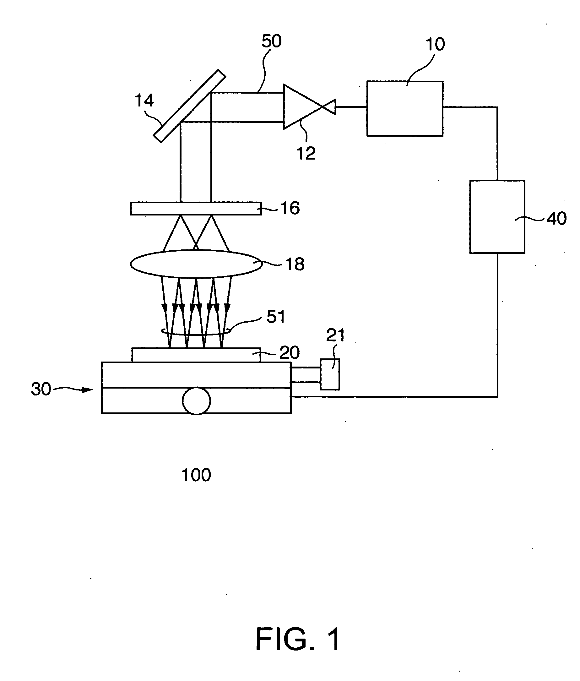
[0034]FIG. 1 is a diagram to explain a laser processing apparatus according to the embodiment of the present invention.

[0035] As shown in FIG. 1, the laser processing apparatus 100 of the present embodiment is configured including a laser generator 10, a diffraction grating 16, a lens 18, precision positioning tables 30, and a control 40 controll...


PUM

PropertyMeasurementUnit
distanceaaaaaaaaaa
distanceaaaaaaaaaa
speedaaaaaaaaaa

Abstract

A laser processing apparatus is provided including: a laser generator generating a light beam; a branching means for branching out the light beam to a plurality of beams arranged at equal intervals; a shifting means for shifting the plurality of beams at a pitch equal to a multiple of natural number of the arranged intervals relatively over a target; and a control means for controlling the intensity of the beam synchronously with the shifting pitch of the plurality of beams.

Description

RELATED APPLICATIONS [0001] This application claims priority to Japanese Patent Application No. 2003-384186 filed Nov. 13, 2003 which is hereby expressly incorporated by reference herein in its entirety. BACKGROUND [0002] 1. Field of the Invention [0003] The present invention relates to laser processing technology, and particularly to laser processing technology which excels in mass production. [0004] 2. Related Art [0005] As processing techniques of removing a film formed on a substrate or perforating a substrate, there is employed a method of applying a plurality of beams on one point with a target in a stationary condition. However, in such a method, since processing is performed to each point, in a case where there are a great number of points to be processed, shifting and stopping (acceleration and reduction of speed) of the target is repeated per point to be processed, an enormous period of time is required for processing. [0006] On the other hand, there is a method whereby a ...

Claims


Application Information

Patent Timeline
Patent Type & Authority Applications(United States)
IPC IPC(8): B23K26/00B23K26/067
CPCB23K26/067B23K26/0853B23K26/0676
Inventor SAWAKI, KAZUSHIGESAWAKI, DAISUKE
Owner SEIKO EPSON CORP
Why Eureka
Try Eureka