
Device and method for laser processing

a laser processing and laser processing technology, applied in the field of laser processing equipment and laser processing methods, can solve problems such as errors

Inactive Publication Date: 2006-07-06
HAMAMATSU PHOTONICS KK
View PDF13 Cites 146 Cited by
  • Summary
  • Abstract
  • Description
  • Claims
  • Application Information

AI Technical Summary

Benefits of technology

[0004] Therefore, in view of such circumstances, it is an object of the present invention to provide a laser processing apparatus and laser processing method which can accurately converge laser light for processing the object at a predetermined position.
[0006] In this laser processing apparatus, the first laser light for forming a modified region by multiphoton absorption and the second laser light for measuring the displacement of the laser light irradiation surface of the object are converged on the same axis by the condenser lens onto the object. Here, the light-converging point position control means detects the reflected light of the second laser light reflected by the laser light irradiation surface, and places the light-converging point of the first laser light at a predetermined position within the object. Since the forming of the modified region by the first laser light and the measurement of the displacement of the laser light irradiation surface by the second laser light are performed on the same axis, the position of light-converging point of the first laser light can be prevented from shifting from a predetermined position within the object because of vibrations of a stage mounting the object and the like, for example. Therefore, the first laser light for processing the object can accurately be converged at a predetermined position.
[0008] Preferably, the laser light irradiation surface is a surface of the object on the condenser lens side, whereas the light-converging point position control means regulates the position of light-converging point of the first laser light such that the position of light-converging point of the first laser light is at a predetermined depth from the surface on the condenser lens side. This can stabilize the accuracy of cutting on the surface side of the object when cutting the object from the modified region acting as a start point, for example. Such stabilization of the accuracy of cutting on the surface side is effective in particular when forming the surface of the object with a plurality of functional devices and cutting the object into the individual functional devices, since the functional devices can be prevented from being damaged. The functional devices refer to light-receiving devices such as photodiodes, light-emitting devices such as laser diodes, circuit devices formed as circuits, etc.
[0010] Preferably, a filter transmitting the reflected light of the second laser light but blocking reflected light of the first laser light reflected by the laser light irradiation surface is provided on the optical path of the reflected light of the second laser light. When this filter is employed, the light-converging point position detecting means can accurately detect the reflected light of the second laser light without being influenced by the reflected light of the first laser light, whereby the positional accuracy of the light-converging point of the first laser light can further be improved.
[0012] This laser processing apparatus can accurately converge the first laser light for processing the object at a predetermined position as with the above-mentioned laser processing apparatus for forming a modified region by multiphoton absorption.

Problems solved by technology

However, the following problem exists in the above-mentioned laser processing apparatus.
Namely, since the condenser lens and the measuring means are disposed along with each other with a predetermined gap therebetween, there is a fear of an error occurring between the actual surface height of the object just under the condenser lens and the value measured by the measuring means because of vibrations of a stage mounting the object and the like, whereby the position of light-converging point of laser light may shift from the surface of the object.

Method used


Image

  • Device and method for laser processing
  • Device and method for laser processing
  • Device and method for laser processing

Examples


Embodiment Construction

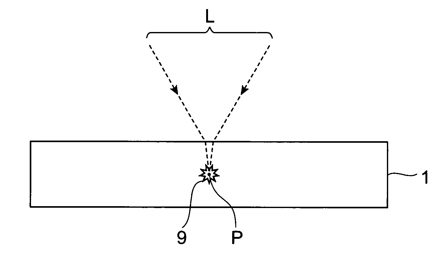
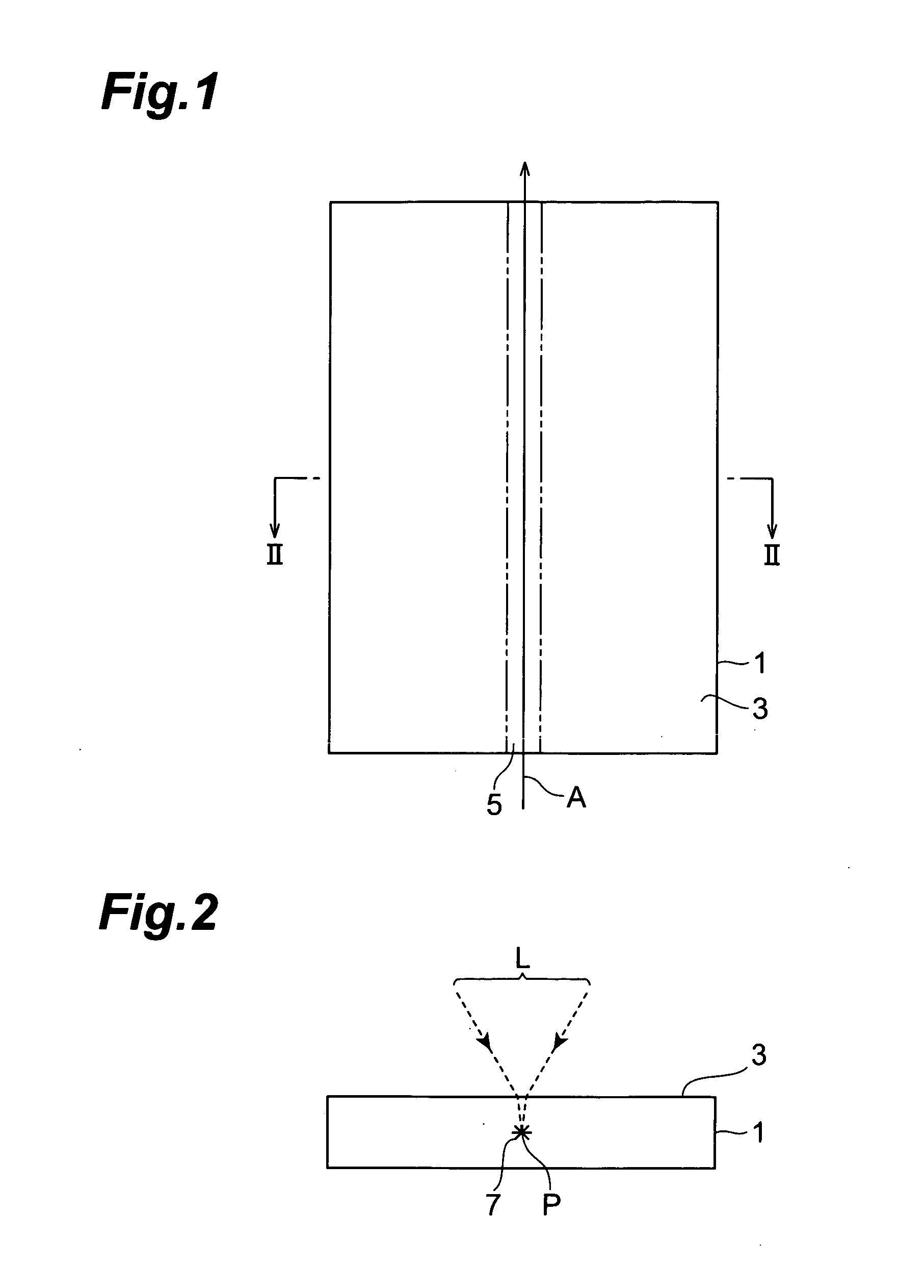
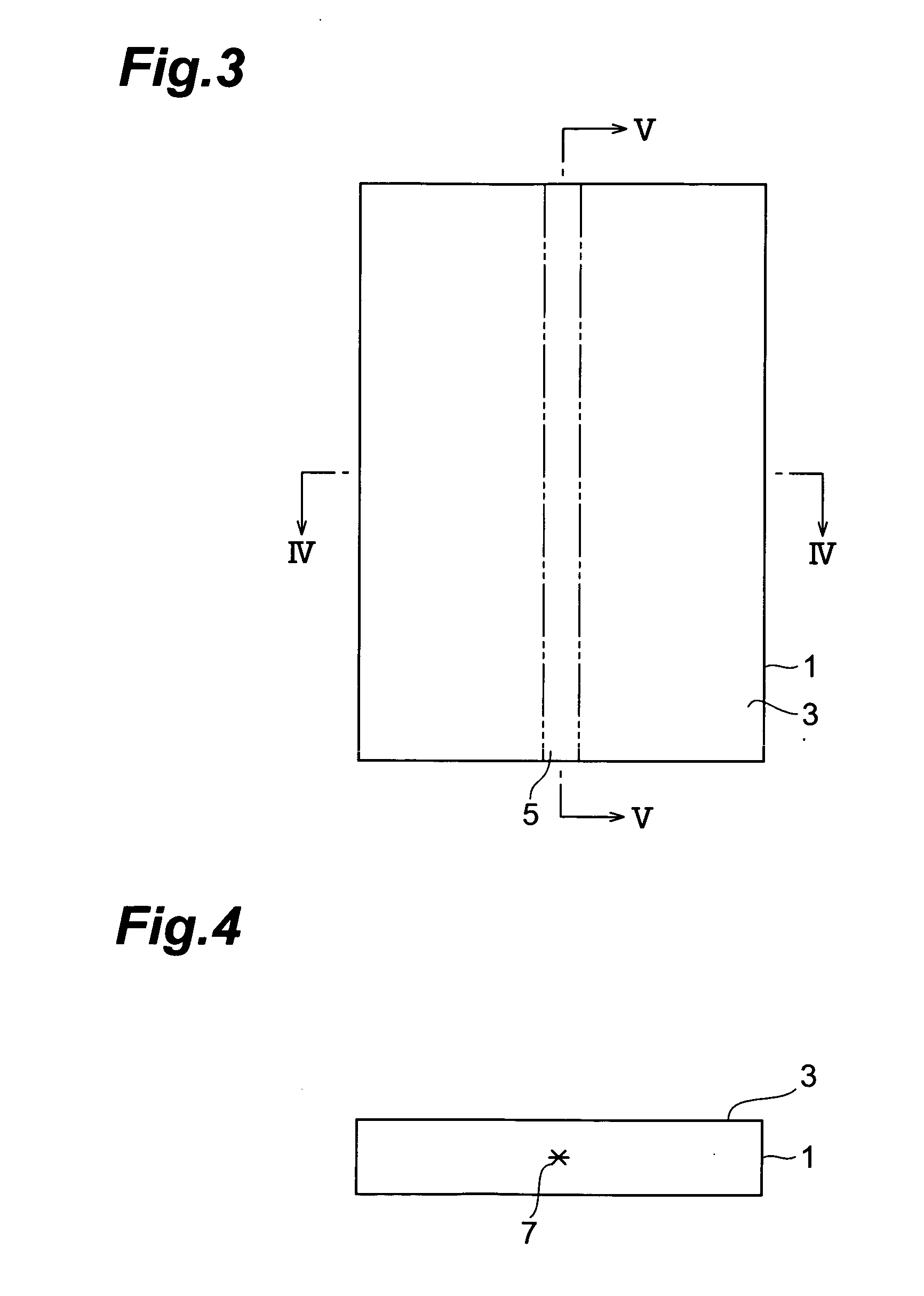
[0034] In the following, preferred embodiments of the laser processing apparatus and laser processing method in accordance with the present invention will be explained in detail with reference to the drawings.

[0035] The laser processing apparatus in accordance with an embodiment irradiates a wafer-like object to be processed while locating a light-converging point within the object, so as to form a modified region by muiltiphoton absorption within the object. Therefore, before explaining the laser processing apparatus in accordance with this embodiment, the forming of a modified region by the multiphoton absorption will be explained.

[0036] A material becomes transparent when its absorption bandgap EG is greater than photon energy hv. Hence, a condition under which absorption occurs in the material is hv>EG. However, even when optically transparent, the material generates absorption under a condition of nhv>EG (where n=2, 3, 4, . . . ) if the intensity of laser light becomes very h...


PUM

PropertyMeasurementUnit
Depthaaaaaaaaaa
Distanceaaaaaaaaaa
Optical propertiesaaaaaaaaaa

Abstract

A laser processing apparatus and a laser processing method which can accurately converge processing laser light at a predetermined position are provided. In the laser processing apparatus, a condenser lens 31 converges processing laser light L1 and rangefinding laser light L2 onto an object to be processed 1 on the same axis. Here, light-converging point position control means40 detects reflected light L3 of the rangefinding laser light reflected by the front face 3 of the object 1, and places a light-converging point P1 of the processing laser light L1 at a predetermined position. Since the processing by the processing laser light L1 and the measurement of displacement of the front face 3 by the rangefinding laser light L2 are carried out on the same axis as such, the light-converging point P1 of processing laser light L1 can be prevented from shifting from the predetermined position because of vibrations of the stage 21 and the like. Therefore, the processing laser light L1 can accurately be converged at the predetermined position.

Description

TECHNICAL FIELD [0001] The present invention relates to a laser processing apparatus and laser processing method for processing an object to be processed by irradiating it with laser light. BACKGROUND ART [0002] Known as a conventional laser processing apparatus is one in which measuring means (contact-type displacement meter, ultrasonic rangefinder, etc.) for measuring the surface height of the object is provided along with a condenser lens for converging laser light for processing an object to be processed (see, for example, FIGS. 8 to 10 of Japanese Patent Application Laid-Open No. 2002-219591) with a predetermined gap therebetween. For scanning laser light along a surface of an object to be processed, such a laser processing apparatus measures the surface height of the object by the measuring means, and drives the condenser lens along its optical axis such that the distance between the condenser lens and the surface of the object becomes constant according to the measured value ...

Claims


Application Information

Patent Timeline
IPC IPC(8): B23K26/16B28D5/00B23K26/00B23K26/046B23K26/38B23K26/40B23K101/40B28D1/22H01L21/301
CPCB23K26/0057B23K26/046B28D1/221B23K26/4075B23K26/048B23K26/40B23K26/53B23K2103/50H01S3/10
Inventor FUKUMITSU, KENSHIFUKUYO, FUMITSUGUKUNO, KOJI
Owner HAMAMATSU PHOTONICS KK
Learn More