Target localization using TDOA distributed antenna

a distributed antenna and target technology, applied in direction finders, instruments, measurement devices, etc., can solve the problems of difficult to locate targets, large geometric dilution of precision (gdop), and limited response speed of associated analysis equipment, so as to achieve high direction and location finding accuracy.

Active Publication Date: 2005-02-17
SAAB INC
View PDF4 Cites 133 Cited by
  • Summary
  • Abstract
  • Description
  • Claims
  • Application Information

AI Technical Summary

Benefits of technology

It is an object of the present invention to overcome the problems of the prior art by providing a system and methods for high direction and location finding accuracy utilizing exi

Problems solved by technology

Typically these approach radar systems require large rotating antennas making them expensive.
In addition, these radar systems characteristically have an update rate of approximately 4.5 seconds, and consequently the response speed of the associated analysis equipment is limited by the update rate of the radar.
However, if it is required to provide large area coverage around the multilateration system, the ratio of the antenna baseline (distance between the receivers) to the range of the target becomes such that the Geometric Dilution of Precision (GDOP) becomes quite large.
It therefore becomes more difficult to locate the target within the “ellipse of uncerta

Method used


Image

  • Target localization using TDOA distributed antenna
  • Target localization using TDOA distributed antenna
  • Target localization using TDOA distributed antenna

Examples


Embodiment Construction

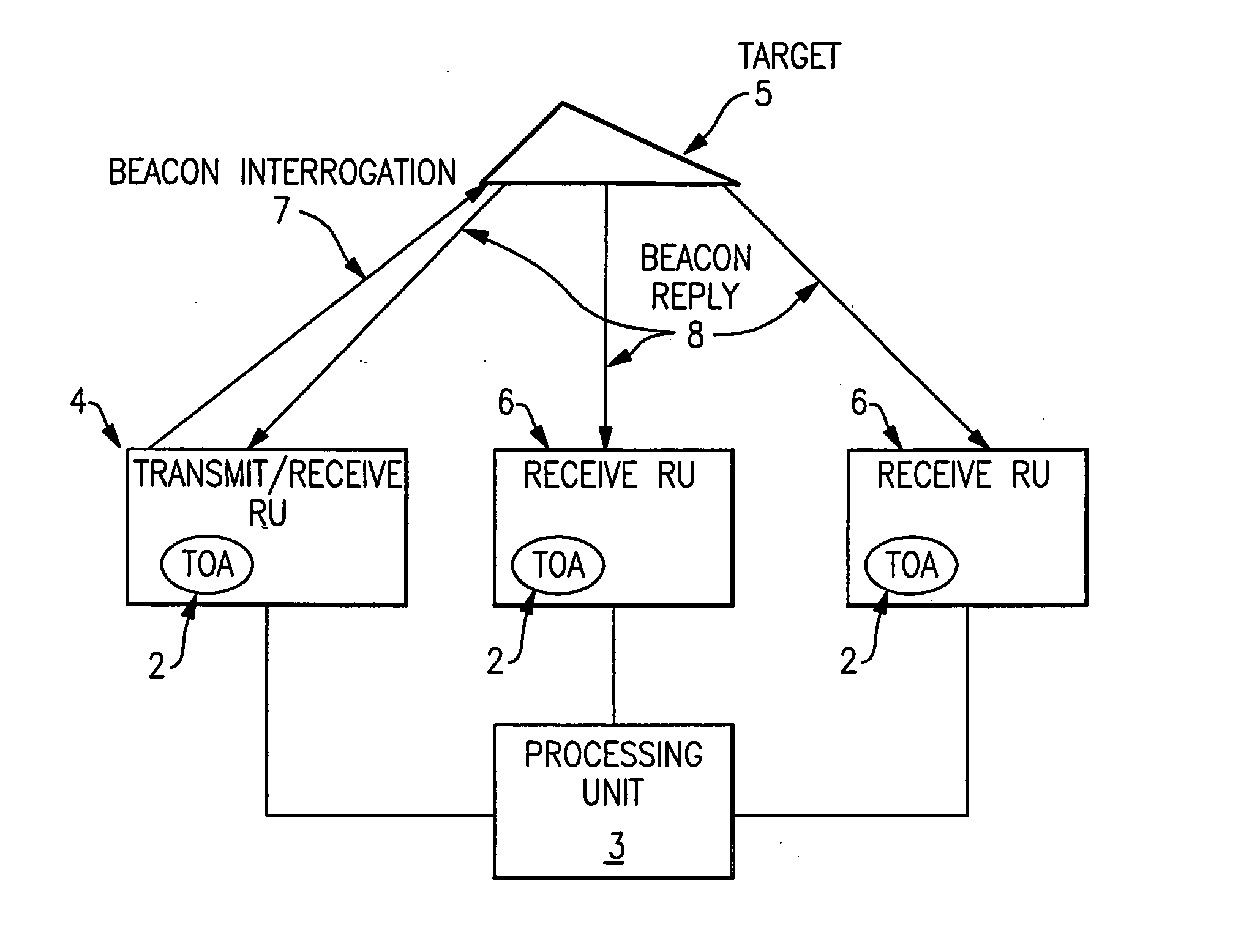
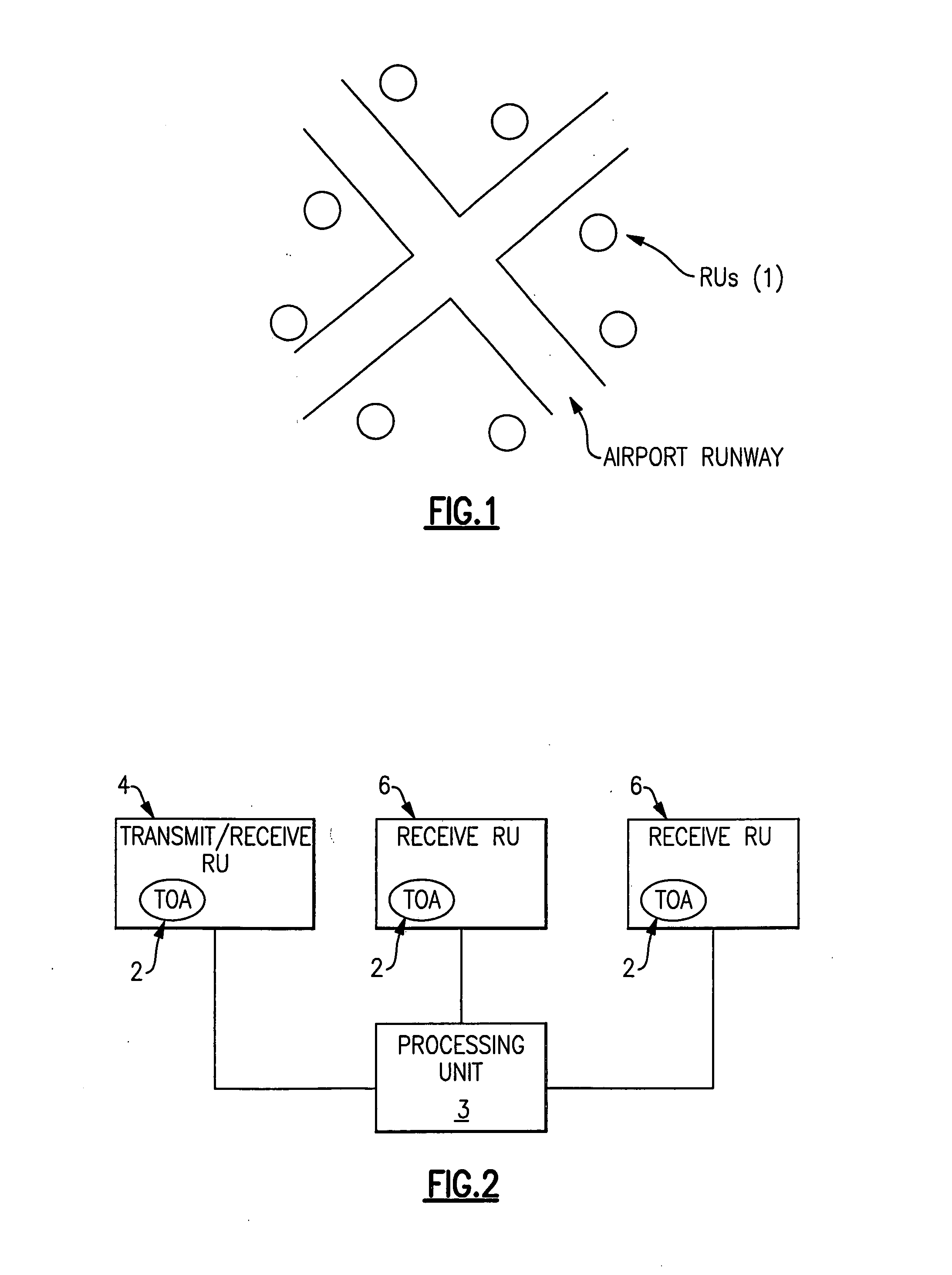
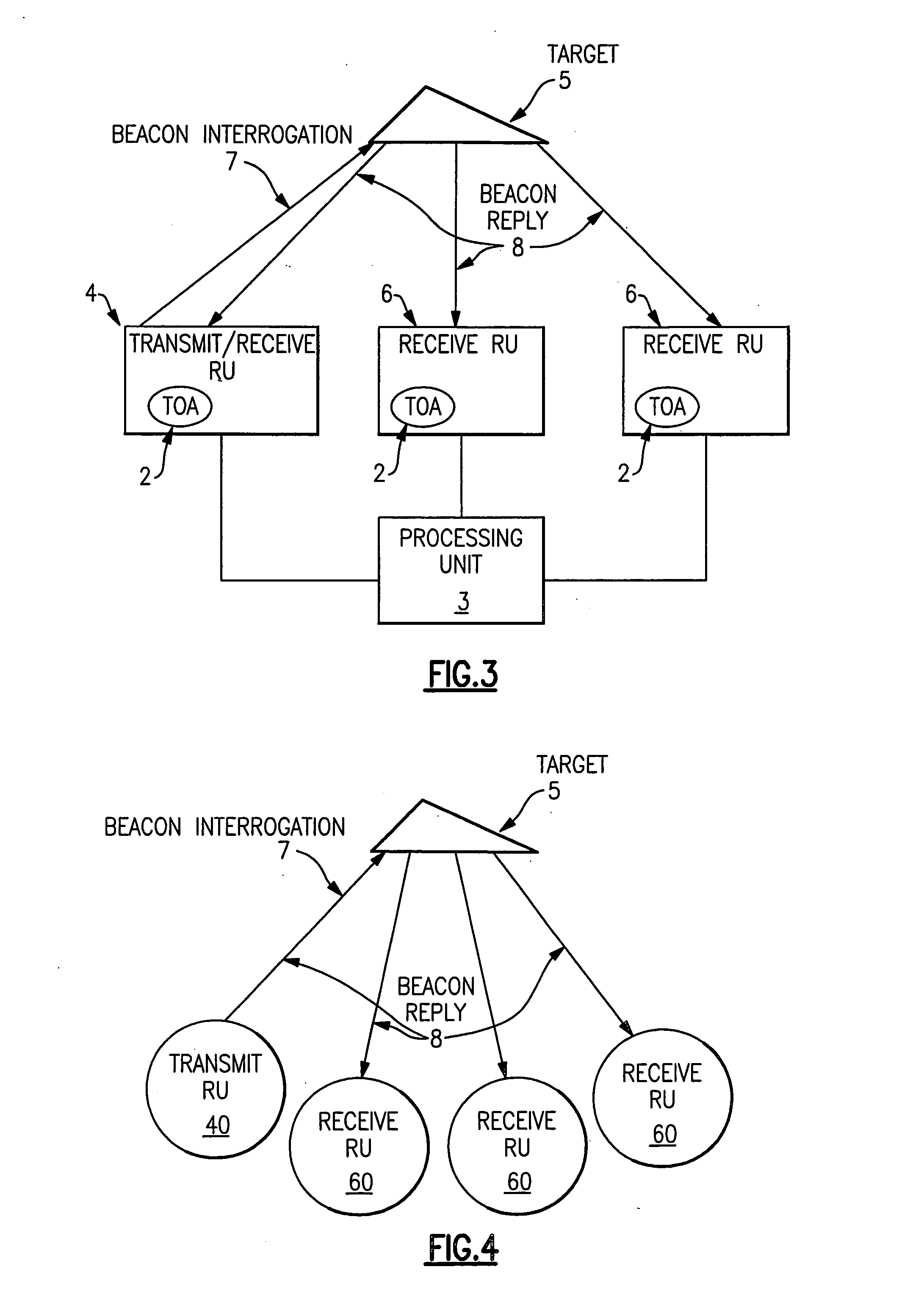
One embodiment of the present invention will now be described with reference to FIGS. 1-9. A number of antenna elements 1 (hereafter referred to as “receiving units” (RUs)) are placed in known positions within the airport confines to create an antenna array as depicted in FIG. 1. A typical RU is sold by Sensis Corporation (Model No. 100-008121-G001). The distance and placement of the RUs is referred to as the antenna array baseline or baseline. In this embodiment, any combination of at least one transmitter and three receivers is required to provide three-dimensional localization of targets in and around the airport. The RUs can receive only, transmit only, or both transmit and receive. More RUs may be required dependent upon the geography and building layout in and around the airport in order to overcome Line of Sight (LOS) obstructions and multipath issues. In accordance with the present invention, all of the RUs can be positioned within the confines of the airport, thus insuring...


PUM


Abstract

This invention is a system and method of locating a target using distributed antenna. The antenna consists of several receiving elements in known locations. At least one of the receiving elements is also a transmitter and transmits an interrogation signal to a target. The return signal from the target is received by a plurality of receiving elements and the target's position is calculated using the time of arrivals of the reply signal and the round trip delay between the transmission of the interrogation signal and the reception of the subsequent reply signal.

Description

FIELD OF THE INVENTION The invention relates to ground-based or airborne air traffic surveillance systems, particularly to direction finding and target localization using a TDOA (Time Differential of Arrival) distributed antenna. BACKGROUND OF THE INVENTION In the current art a number of systems and methodologies exist for the localization of ground vehicles and aircraft (e.g., targets) in and around air traffic surveillance systems which can include airports, terminal areas and en route systems. Many large airports utilize approach radar systems to locate and track targets outside the airport. These radar systems obtain good azimuth accuracy by using the narrow beam available from the large aperture antenna, whereas the range is calculated from the round trip delay of the signal from the radar to the target and back. Typically these approach radar systems require large rotating antennas making them expensive. In addition, these radar systems characteristically have an update rat...

Claims


Application Information

Patent Timeline
IPC IPC(8): G01S5/02G01S5/12G01S5/14G01S13/87
CPCG01S13/878G01S5/12
Inventor PERL, ELYAHUGERRY, MICHAEL J.
Owner SAAB INC
Why Eureka
Try Eureka