Electric rotating machine

a rotating machine and electric technology, applied in the direction of magnetic circuit rotating parts, magnetic circuit shape/form/construction, windings, etc., can solve the problems of rotational vibration, heatproof temperature the higher the cost, and limit the heatproof temperature, so as to improve the cooling capacity and construction cheaply. , the effect of improving the cooling capacity

Inactive Publication Date: 2002-02-12
MITSUBISHI HITACHIPOWER SYST LTD
View PDF6 Cites 45 Cited by
  • Summary
  • Abstract
  • Description
  • Claims
  • Application Information

AI Technical Summary

Benefits of technology

An object of the present invention is to provide an electric rotating machine, which can be constructed cheaply while improving the cooling capacity at the end portions of the rotor coils, as well as being small in the size and large in the capacity, with superior reliability thereof.

Problems solved by technology

As the insulator layers of the rotor coils are used a material having high thermal resistance, such as mica, etc., however there is a limit in the heatproof temperature thereof, therefore there is a tendency that the higher the heatproof temperature the higher the cost thereof.
Also, the thermal expansion of the coil conductor accompanying with the rise-up of temperature gives a large stress or strain on the rotor coils, in particular on the end portions thereof protruding outside the rotor slots, thereby sometimes causing a rotational vibration.
Because of this, the power or capacity of cooling from the surface of the rotor coils, on which the coil support seats and the coil support members lie, is low.
Also, in that of the conventional art 1, there are used the two (2) kinds of materials, such as the coil support member and the coil support seats lying between at both sides thereof, therefore workability is bad in particular in the insertion of those members.

Method used


Image

  • Electric rotating machine
  • Electric rotating machine
  • Electric rotating machine

Examples


Embodiment Construction

Hereinafter, embodiments according to the present invention will be fully explained by referring to the attached drawings.

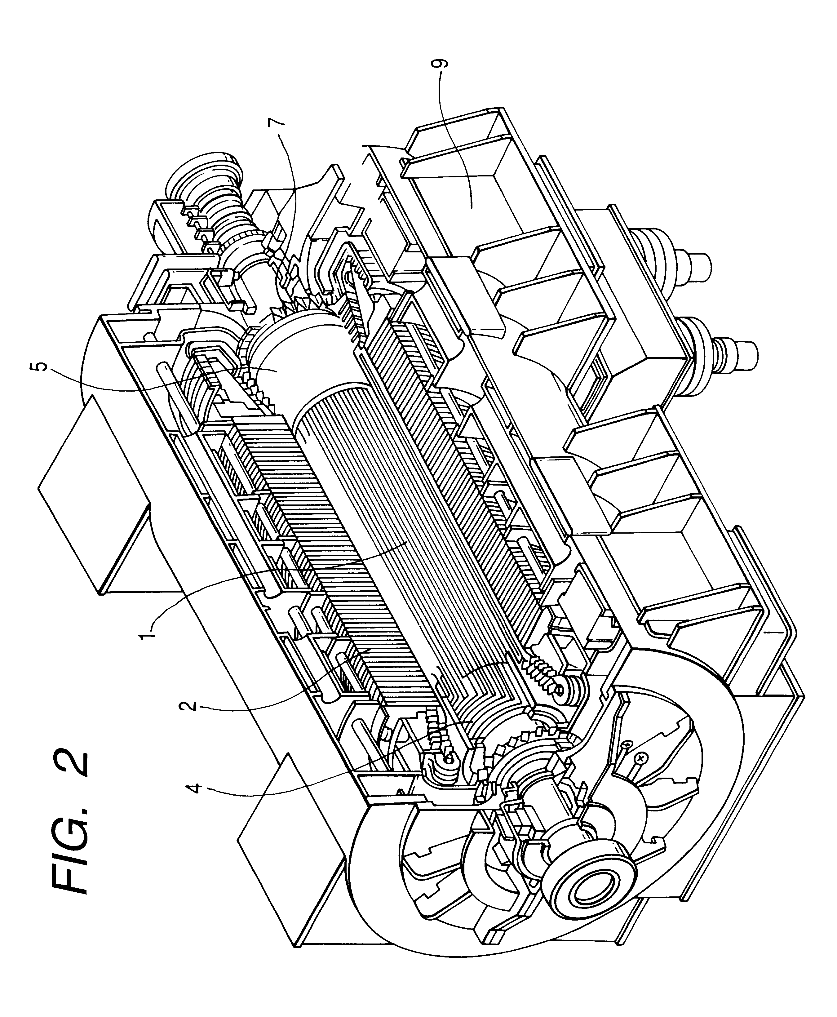
First, explanation will be given on an outline structure of an air cooling type turbine generator, according to the present invention, by referring to FIG. 2. In this embodiment, the explanation will be given on that, in which the air is applied as a fluid of coolant, however it may be a fluid other than the air. A rotor 1 is supported within a stator 2, being freely ratable. A plurality of rotor coils 4, which construct the same magnetic pole, are fixed on the rotor 1, while being positioned around the magnetic pole concentrically. Portions of those rotor coils 4, extending in the axial direction, are held in rotor slots which are formed on an outer surface of the rotor 1 at a distance therebetween. Also, the portions of the rotor coils 4, protruding outside the rotor slots are held by means of a retaining ring 5. The structure of the end portions of the rotor w...


PUM


Abstract

For obtaining an electric rotating machine being constructed cheaply, while cooling capacity at the end portions of the rotor coils can be improved, and being small in the size and large in the capacity, with superior reliability thereof, in an electric rotating machine, within which a coolant fluid is circulated, wherein coil support members 13 are positioned at a distance therebetween, in a space defined between the end portions 12B of the plural rotor coils, each of the coil support members 13 is formed with two (2) insertion portions 13a extending in a radial direction and a connector portion 13b connecting therebetween, as one body and in an about "H" shape in the cross-section, thereby forming spaces 13c, each of which faces the end portion 12B of the rotor coil, at both sides of the connector portion 13b.

Description

The present invention relates to an electric rotating machine, in particular being suitable for applying to the electric rotating machine of direct gas cooling type having a large capacity.In a conventional generator, in particular, in a turbine generator, a rotor is constructed by inserting a plurality of rotor coils into slots which are formed around a rotor core in the axial direction thereof. Those slots of the rotor are provided on an outer periphery surface of the rotor at a distance therebetween, at both sides of magnetic poles of the rotor core thereof, wherein the plurality of the rotor coils constructing the same magnetic pole are positioned concentrically around the magnetic pole. Those rotor coils are formed by accumulating the coil conductors in a radial direction in plural number of turns, and between the turns is provided an insulating layer. When turning on current to those rotor coils from an outside, necessary electromagnetic fields are generated round the magnetic...

Claims


Application Information

Patent Timeline
Patent Type & Authority Patents(United States)
IPC IPC(8): H02K3/24H02K3/51H02K3/50H02K3/04H02K1/32H02K9/04
CPCH02K3/51H02K3/24
Inventor KIEDA, SHIGEKAZUMORI, HIDEAKISHIOBARA, RYOICHIHATTORI, KENICHI
Owner MITSUBISHI HITACHIPOWER SYST LTD
Why Eureka
Try Eureka