Fuel cell vehicle and control method thereof

a fuel cell and vehicle technology, applied in the direction of electric energy management, propulsion parts, electric devices, etc., can solve the problems of reducing fuel economy, affecting the efficiency of fuel cell vehicles, so as to improve fuel economy, reduce the loss of dc-dc converters, and simple and economical structure

Inactive Publication Date: 2006-02-02
HONDA MOTOR CO LTD
View PDF3 Cites 21 Cited by
  • Summary
  • Abstract
  • Description
  • Claims
  • Application Information

AI Technical Summary

Benefits of technology

[0013] A main object of the present invention is to provide a fuel cell vehicle having a simple and economical structure and a method of controlling the fuel cell vehicle in which the loss in a DC-DC converter is reduced, and it is possible to improve fuel economy.
[0019] In the present invention, when regeneration by the energy storage is performed, the DC-DC converter connected to the energy storage is in the direct connection mode. Therefore, no voltage adjustment (switching) by the DC-DC converter is required. Thus, it is possible to effectively reduce the switching loss in the DC-DC converter. With the simple and economical structure, regeneration energy is collected effectively to ensure improvement in fuel economy.

Problems solved by technology

Therefore, the switching loss occurs in the DC-DC converter 6, and part of the regeneration energy is lost.
Consequently, the fuel economy is degraded.

Method used


Image

  • Fuel cell vehicle and control method thereof
  • Fuel cell vehicle and control method thereof
  • Fuel cell vehicle and control method thereof

Examples


first embodiment

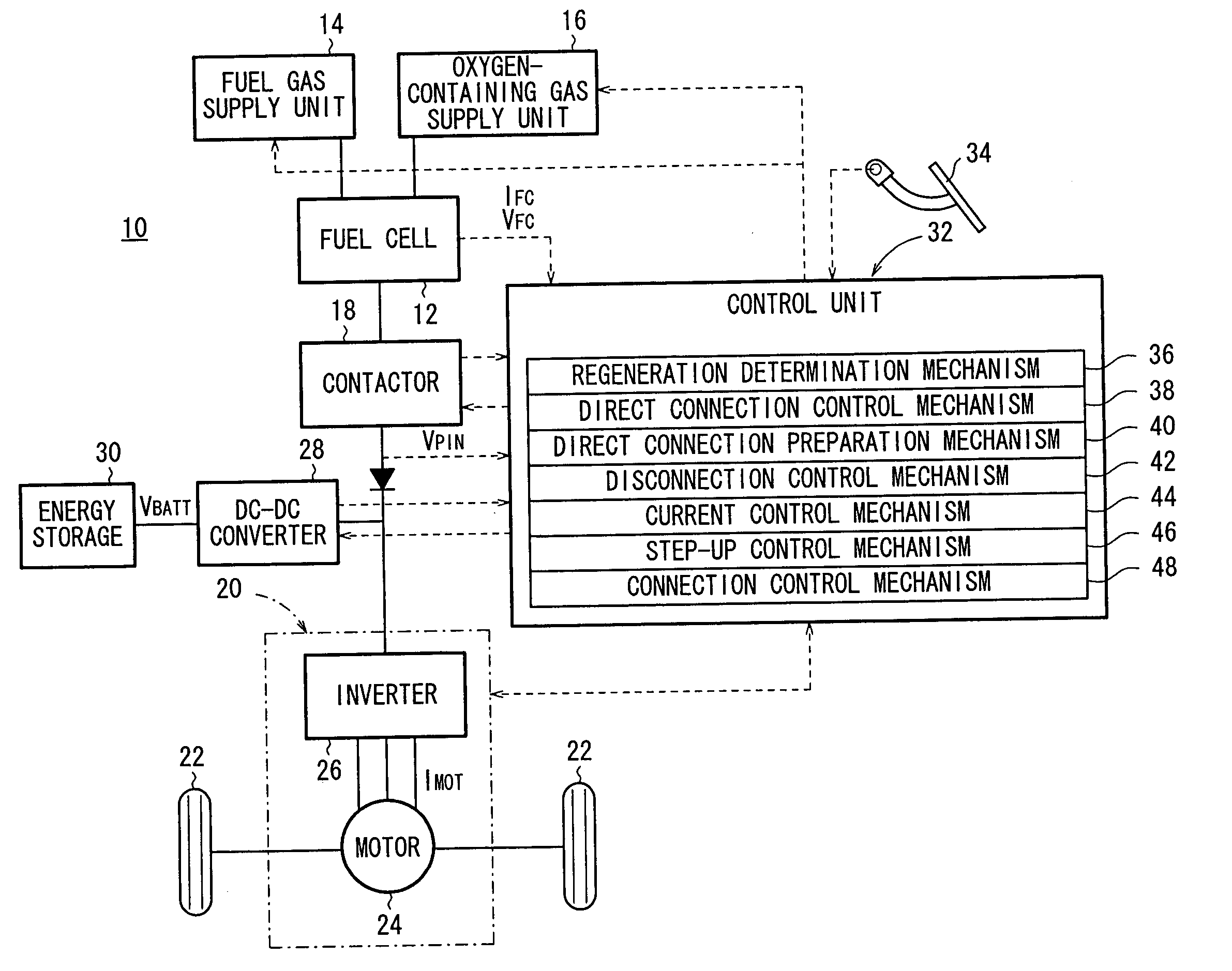
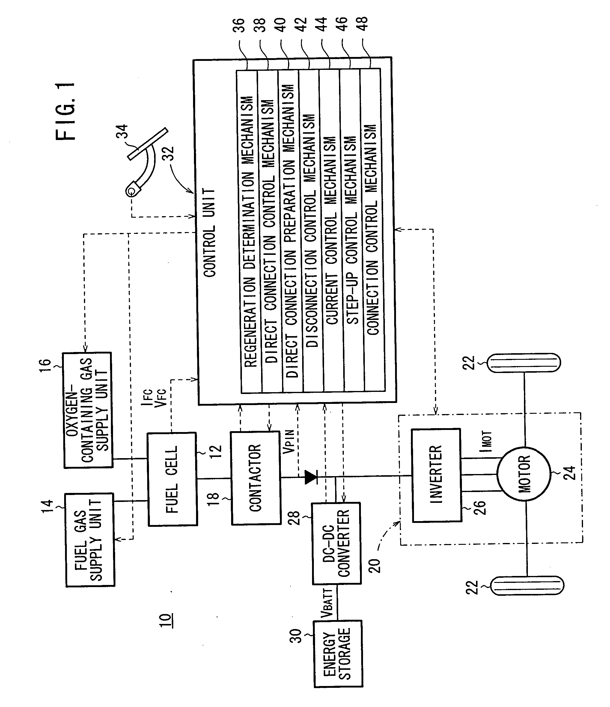
[0032]FIG. 1 is a diagram schematically showing structure of a fuel cell vehicle 10 for carrying out a control method according to the present invention.

[0033] The fuel cell vehicle 10 includes a fuel cell 12. A fuel gas supply unit 14 and an oxygen-containing gas supply unit 16 are connected to the fuel cell 12. Further, a coolant supply unit (not shown) is connected to the fuel cell 12 as necessary. Though not shown, the fuel cell 12 comprises a stack of power generation cells each including a membrane electrode assembly and a pair of separators sandwiching the membrane electrode assembly. The membrane electrode assembly includes an anode, and a cathode, and a solid polymer electrolyte membrane interposed between the anode and the cathode.

[0034] The fuel gas supply unit 14 supplies a fuel gas such as a hydrogen-containing gas to the anode of the fuel cell 12, and the oxygen-containing gas supply unit 16 supplies an oxygen-containing gas such as air to the cathode of the fuel cell...

second embodiment

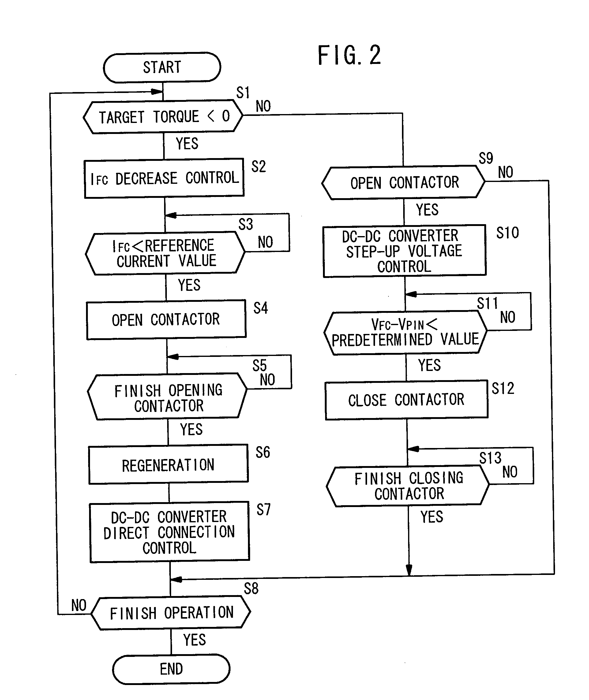
[0056] In the second embodiment, if the regeneration determination mechanism 36 determines that the target torque is negative (YES in step S21), the routine proceeds to step S22, and the current control mechanism 44 performs the control to decrease the fuel cell current IFC, and power regeneration is started. Thus, the regeneration electrical energy of the motor 24 is charged in the energy storage 30 by the opening and closing control of the DC-DC converter 28.

[0057] Then, if it is determined that the fuel cell current IFC is the reference current value IPD or less (YES in step S23), the routine proceeds to step S24. Thus, after the contactor 18 is opened under control, the direct connection control mechanism 38 is placed in the direct connection mode such that the DC-DC converter 28 is constantly in the ON state (step S26).

[0058] In the second embodiment, while the DC-DC converter 28 is in the direct connection mode, it is possible to charge the regeneration electrical energy of t...


PUM

PropertyMeasurementUnit
electrical energyaaaaaaaaaa
currentaaaaaaaaaa
voltageaaaaaaaaaa

Abstract

A fuel cell vehicle includes a fuel cell, a rotating load, a energy storage, a contactor, a DC-DC converter, and a control unit. When regeneration by the energy storage is performed, the DC-DC converter connected to the energy storage is placed in a direct connection mode for directly charging regeneration electrical energy from a motor of the rotating load to the energy storage.

Description

BACKGROUND OF THE INVENTION [0001] 1. Field of the Invention [0002] The present invention relates to a fuel cell vehicle including a fuel cell capable of generating electrical energy by electrochemical reaction of a reactant gas and outputting the electrical energy to a rotating load, a rechargeable energy storage, a switching mechanism for electrically connecting the fuel cell to the rotating load and the energy storage or electrically disconnecting the fuel cell from the rotating load and the energy storage, and a DC-DC converter connected to the energy storage. Further, the present invention relates to a method of controlling the fuel cell vehicle. [0003] 2. Description of the Related Art [0004] A fuel cell is a system that supplies a fuel gas (chiefly containing hydrogen) to an anode and supplies an oxygen-containing gas (chiefly containing oxygen) to a cathode to induce electrochemical reaction for generating DC electrical energy. [0005] For example, a solid polymer fuel cell e...

Claims


Application Information

Patent Timeline
Patent Type & Authority Applications(United States)
IPC IPC(8): B60L11/18H01M16/00H01M10/44H01M8/04
CPCB60L7/14Y02T10/7283B60L11/1866B60L11/1887B60L11/1892B60L15/2045B60L2210/14B60L2220/14B60L2240/423H01M8/04298H01M8/0488H01M8/0491H01M8/0494H01M10/44H01M16/006H01M2250/20H01M2250/407Y02E60/563Y02T90/32Y02T90/34Y02E60/50Y02T10/7225Y02T10/7061Y02T10/642B60L11/1803B60L50/51B60L58/22B60L58/33B60L58/40Y02E60/10Y02T10/64Y02T10/70Y02T10/72Y02T90/40
Inventor SAEKI, HIBIKIAOYAGI, SATOSHI
Owner HONDA MOTOR CO LTD
Why Eureka
Try Eureka