Series connected light string with filament shunting

a technology of connected light strings and filaments, which is applied in the direction of lighting and heating apparatus, transportation and packaging, and support devices, etc., can solve the problems of inability to further solve additional problems, the short circuiting feature of the bulb does not always operate in the manner, and the entire string will go out, etc., to achieve simple and inexpensive, simple and economical construction, and the effect of simple and inexpensiv

Inactive Publication Date: 2006-08-08
JLJ
View PDF22 Cites 19 Cited by
  • Summary
  • Abstract
  • Description
  • Claims
  • Application Information

AI Technical Summary

Benefits of technology

[0017]It is therefore a principal object of the present invention to provide a simple and inexpensive silicon type filament shunt, or bypass, for each of a plurality of series connected light bulbs, said filament shunt having a predetermined conductive switching value which is only slightly greater than the voltage rating of said bulbs, and which shunt becomes conductive whenever the peak voltage applied thereacross exceeds its said predetermined voltage switching value, which would occur for any of the reasons previously stated, and which provides continued and uninterrupted flow of rated current through each of the remaining bulbs in the string, together with substantially unchanged illumination in light output therefrom.
[0018]It is another object of the present invention to provide a new and improved series-connected light bulb string which has the desirable features set forth above, and yet is of very simple and economical construction and is relatively inexpensive to manufacture in mass quantities, thereby keeping the overall cost of the final product on the marketplace at a minimum, and which does not necessitate any type of bulb which is specially designed to provide a short circuit whenever it burns out, as is presently the case in substantially all strings on the market.
[0019]It is still another object of the present invention to provide a series-connected light bulb string having all of the features set forth above, and in which the light emitted from each light bulb will optionally appear, disappear, and reappear independently and continuously along the entire string, thereby creating a most striking, novel and unusual twinkling effect.

Problems solved by technology

However, in actual practice, it has been found that such short circuiting feature within the bulb does not always operate in the manner intended and the entire string will go out whenever a single bulb burns out.
Even though each of the foregoing techniques have met with some limited success, none of such devices and techniques have yet been able to further solve the additional problems of the entire string of lights going out as a direct result of either a defective socket, a light bulb being improperly placed in the socket, a broken or bent wire of a light bulb, or whenever a light bulb is either intentionally removed from its socket or is merely dislodged from its socket during handling or from movement after being strung on the Christmas tree, particularly in outdoor installations subject to wind or other climatic conditions.
It is stated therein that the use of either a single or a plurality of parallel connected Zener diodes will not protect the lamps against normal failure caused by normal current flows, but will protect against failures due to excessive current surges associated with the failure of associated lamps.
However, to the knowledge of Applicant, none of such arrangements have ever become commercially feasible.
Some of these prior art shunts cause a reduced current flow in the series string because of too high of a voltage drop occurring across the shunt when a bulb becomes inoperable, either due to an open filament, a faulty bulb, a faulty socket, or simply because the bulb is not mounted properly in the socket, or is entirely removed or falls from its respective socket.
However, other shunt devices cause the opposite effect due to an undesired increase in current flow.
For example, when the voltage dropped across a socket decreases, then a higher voltage is applied to all of the remaining bulbs in the string, which higher voltage results in higher current flow and a decreased life expectancy of the remaining bulbs in the string.
Additionally, such higher voltage also results in increased light output from each of the remaining bulbs in the string, which may not be desirable in some instances.
However, when the voltage dropped across a socket increases, then a lower voltage is applied to all of the remaining bulbs in the series connected string, which results in lesser current flow and a corresponding decrease in light output from each of the remaining bulbs in the string.
Such undesirable effect occurs in all of the prior art attempts, including those which, at first blush, might be considered the most promising techniques, especially the proposed use of a diode in series with a bilateral switch in the Fleck '449 patent, or the proposed use of a metal oxide varistor in the above Harnden '966 patent, or the use of the proposed counter-connected rectifiers in the Swiss '021 patent.
Additionally, as such an arrangement does not permit more that one bulb to be out at the same time, certain additional desirable special effects such as “twinkling”, and the like, obviously would not be possible.
In the arrangement suggested in Harnden '966 patent, Harden proposes to utilize a polycrystalline metal oxide varistor as the shunting device, notwithstanding the fact that it is well known that metal oxide varistors are not designed to handle continuous current flow therethrough.
They are designed for use as spike absorbers and are not designed to function as a voltage regulator or as a steady state current dissipation circuit.
While metal oxide varistors may appear in some cases similar to back-to-back Zener diodes, they are not interchangeable and function very differently according to their particular use.
This low value of resistance results in a substantial increase in the voltage being applied to the remaining bulbs even when only a single bulb is inoperative for any of the reasons previously stated.
Thus, when multiple bulbs are inoperative, a still greater voltage is applied to the remaining bulbs, thereby again substantially increasing their illumination, and consequently, substantially shortening their life expectancy.
In contrast, by utilizing a shunt of the type proposed by Applicant, substantially all of the bulbs in a 50 bulb string can become inoperative for any or all of the reasons previously stated, with only a minimal decrease in intensity of illumination of the remaining bulbs, which is not possible with any of the foregoing shunts.
Obviously, such a scheme is not always effective, particularly when a bulb is removed from its socket or becomes damaged in handling, etc.
While this particular locking technique apparently is very effective to keep bulbs from falling from their respective sockets, the replacement of defective bulbs by the average user is extremely difficult, if not sometimes impossible, without resorting to mechanical gripping devices which can actually destroy the bulb base unit or socket.

Method used


Image

  • Series connected light string with filament shunting
  • Series connected light string with filament shunting
  • Series connected light string with filament shunting

Examples


Embodiment Construction

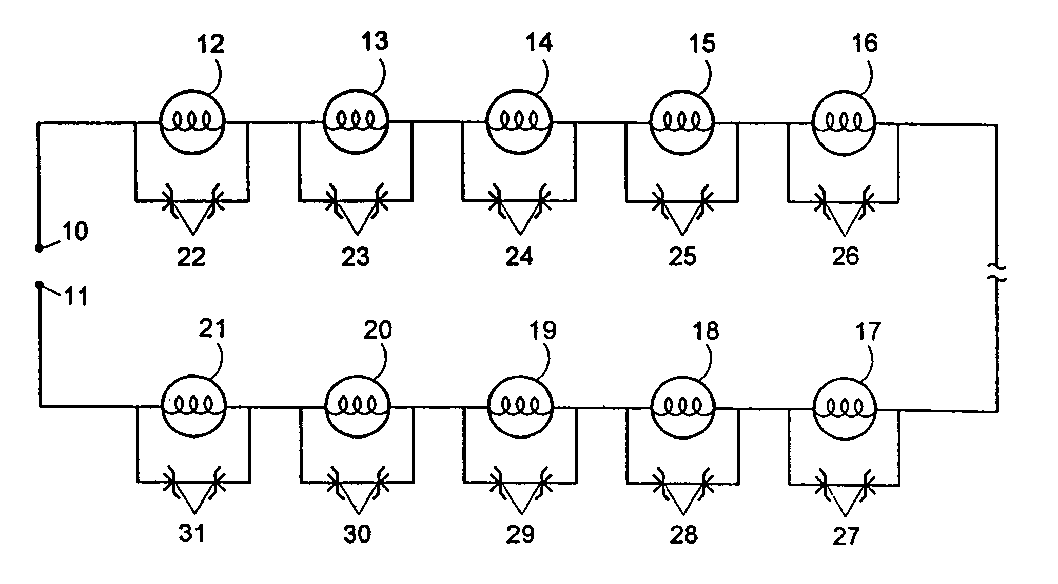
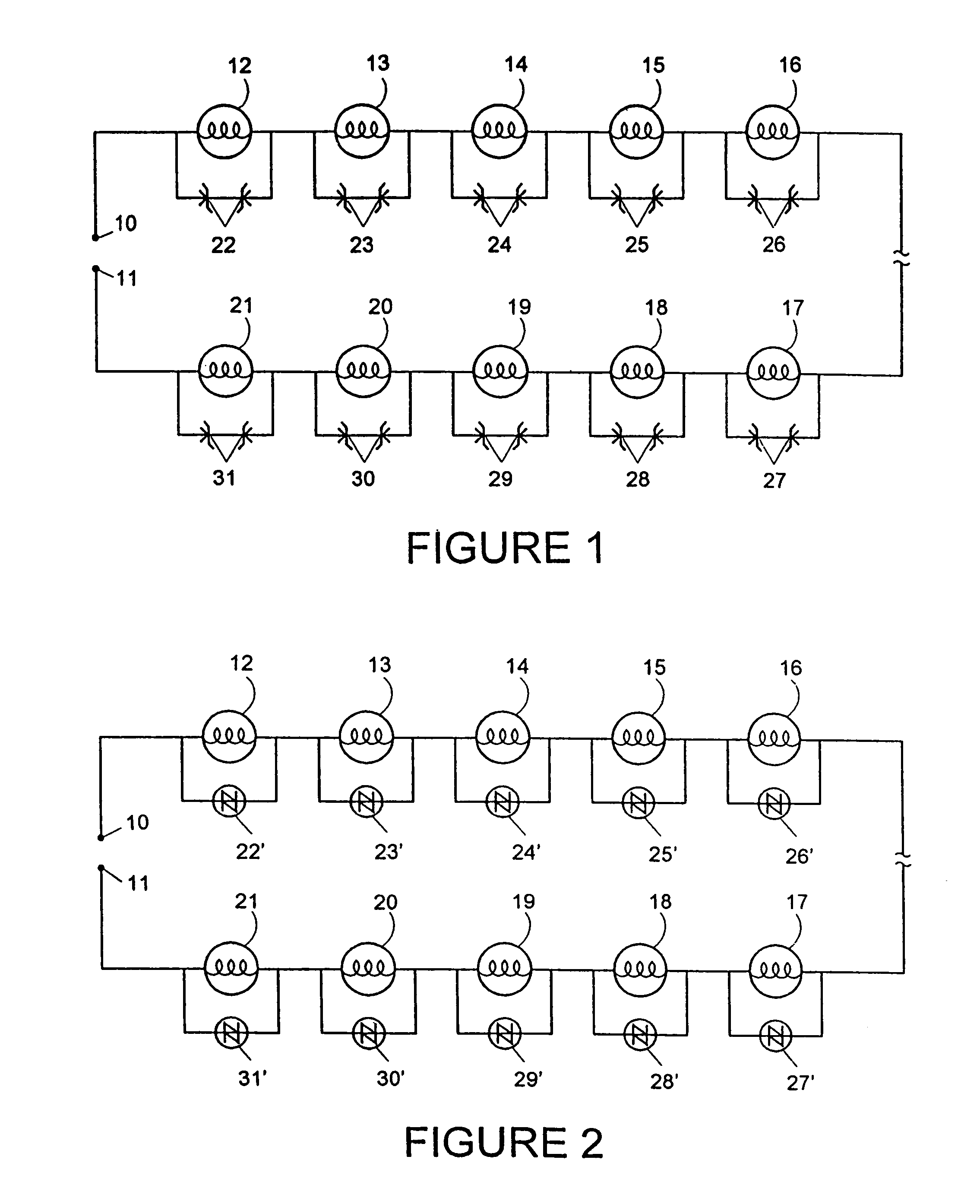
[0026]With reference to the schematic diagram in FIG. 1, the novel light string constructed in accordance with the first embodiment of the present invention comprises input terminals 10 and 11 which are adapted to be connected to a suitable source of supply Of 110 / 120 volts of alternating current normally found in a typical household or business. Terminal 10 is normally fixedly connected to the first terminal of the first socket having a first electrical light bulb 12 operatively plugged therein. The adjacent terminal of the first socket is electrically connected to the adjacent terminal of the second socket having a second light bulb 13 operatively plugged therein, and so on, until each of the light bulbs in the entire string (whether a total of 10 bulbs, as diagrammatically shown, or a total of 50 as is typically the case) are finally operatively connected in an electrical series circuit between input terminals 10 and 11. Operatively connected in an electrical parallel across the ...


PUM


Abstract

A string set of series-connected incandescent bulbs in which substantially all of the bulb filaments in the set are individually provided with a shunt circuit which includes a voltage responsive switch which is inoperative during normal operation of the string set when connected to a source of operating potential and which becomes operative only in response to an increase in the voltage thereacross which exceeds its rating, and in which the remaining bulbs of the circuit continue to receive current therethrough and continue to be illuminated at substantially constant illumination even though other or substantially all of the other bulbs in the string are either inoperative or are missing from their respective sockets.

Description

[0001]This is a continuation-in-part of application of Ser. No. 10 / 364,525, filed Feb. 12, 2003 now abandoned, which is a continuation of application Ser. No. 10 / 061,223, filed Feb. 4, 2002, now U.S. Pat. No. 6,580,182, which is a continuation of application Ser. No. 09 / 526,519, filed Mar. 16, 2000, abandoned, which is a division of application Ser. No. 08 / 896,278 filed Jul. 7, 1997, now abandoned, which is a continuation of application Ser. No. 08 / 653,979, filed May 28, 1996, now abandoned, which is a continuation-in-part of application Ser. No. 08 / 560,472, filed Nov. 17, 1995, now abandoned which, in turn, is a continuation-in-part of application Ser. No. 08 / 494,725, filed Jun. 26, 1995, now abandoned.TECHNICAL FIELD[0002]One of the most common uses of light strings is for decoration and display purposes, particularly during Christmas and other holidays, and more particularly for the decoration of Christmas trees, and the like. Probably the most popular light set currently availab...

Claims


Application Information

Patent Timeline
Patent Type & Authority Patents(United States)
IPC IPC(8): F21S13/14H05B37/03H05B39/10
CPCH05B39/105H05B37/036H05B47/23
Inventor JANNING, JOHN L.
Owner JLJ
Why Eureka
Try Eureka