
Assembly for automatically compensating variations in the spacing between two structural members

a technology of automatically compensating and structural members, which is applied in the direction of threaded fasteners, screws, washers, etc., can solve the problems of relative high manufacturing and mounting costs, and achieve the effect of simple and economical construction and additional structural and operational advantages

Inactive Publication Date: 2005-03-10
BOLLHOFF VERBINDUNGSTECHNIK GMBH
View PDF29 Cites 22 Cited by
  • Summary
  • Abstract
  • Description
  • Claims
  • Application Information

AI Technical Summary

Benefits of technology

[0005] It is is a general object of the invention to provide an improved assembly for compensating variations in the spacing between first and second structural members due to manufacturing and / or mounting tolerances, which avoids the disadvantages of the prior assemblies while affording additional structural and operational advantages. These improvements are to be provided while maintaining the relatively simple and economical construction of the prior compensating assembly.
[0006] According to one aspect of the invention said drive portion of said adjustment sleeve comprising an internal annular plastic portion of said adjustment sleeve, which internal annular plastic portion projects from the wall of the thru-bore of the adjustment sleeve radially inwards sufficiently so as to provide said frictional drag between said drive portion and said external threads of said mounting bolt. Preferably, said adjustment sleeve has an external annular plastic portion projecting beyond said external threads of said adjustment sleeve radially outwards sufficiently so as to allow for frictional or positive engagement between said external annular plastic portion and said base element when said adjustment sleeve is threaded into the base element for securing purposes. Preferably, said internal and external annular plastic portions are interconnected by plastic webs extending through radial bores of said adjustment sleeve. This allows to make the two annual plastic portions by a single injection molding operation.

Problems solved by technology

All these assemblies are relatively complex in that they require a relatively large number of components resulting in relatively high manufacturing and mounting costs.

Method used


Image

  • Assembly for automatically compensating variations in the spacing between two structural members
  • Assembly for automatically compensating variations in the spacing between two structural members

Examples


Embodiment Construction

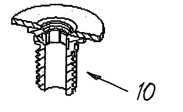
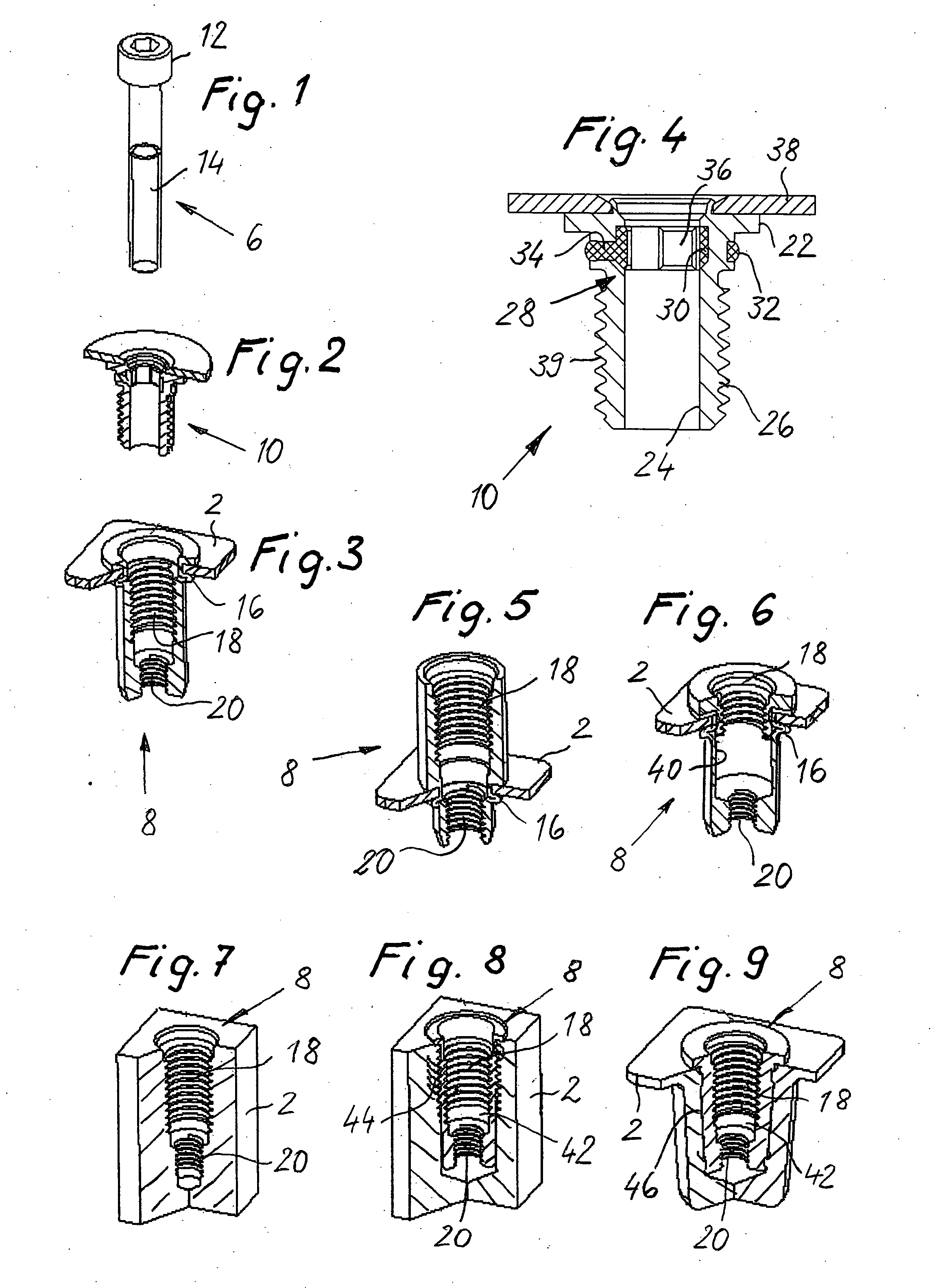
[0019] The assembly for automatically compensating variations as shown in the drawings is basically made up of three components, i.e. a mounting bolt 6 (FIG. 1), a base element 8 (FIG. 3), and an adjustment sleeve 10 (FIG. 2). The basic structure of the assembly as shown is similar to that shown in FIGS. 1 to 4 of the above mentioned DE 101 51 383 A1, the disclosure of which is incorporated herein by reference.

[0020] The assembly for compensating variations is provided to clamp a plate-shaped first structural member 2 (FIG. 3) and a plate-shaped second structural member (not shown) together and at the same time to compensate variations in the spacing between the two pre-assembled structural members which may be caused by manufacturing and / or mounting tolerances.

[0021] The mounting bolt 6 is a conventional bolt such as a standard bolt having a shaft, a head 12, and external threads 14.

[0022] The base element 8 as shown in FIG. 3 is a blind rivet nut which is fixed to the structura...


PUM


Abstract

An assembly for automatically compensating variations of the spacing between first and second structural members due to manufacturing and / or mounting tolerances. The assembly comprises a mounting bolt, a base element, and an adjustment sleeve. The adjustment sleeve has a drive portion adapted to be engaged with the nut by frictional drag and rotatable relative to said mounting bolt when said frictional drag has been overcome. The drive portion comprises an internal annular plastic portion which projects from the wall of the adjustment sleeve radially outwards sufficiently so as to frictionally engage the threads of the mounting bolt to provide for said frictional drag.

Description

BACKGROUND OF THE INVENTION [0001] This invention relates to an assembly for automatically compensating variations in the spacing between first and second structural members due to manufacturing and / or mounting tolerances. [0002] A vast number of assemblies for compensating variations in the spacing between structural members has become known. There have become known also assemblies which allow for automatic compensation of spacing variations, i.e. without any additional action of an operator, in order not to increase assembly time. Such assemblies are shown for example in DE 100 04 697 A1, EP 0 176 663 A1, and EP 0 848 168 A1. All these assemblies are relatively complex in that they require a relatively large number of components resulting in relatively high manufacturing and mounting costs. [0003] Applicant's DE 101 51 383 A1 discloses an assembly for automatically compensating variations of a spacing between first and second structural members due to manufacturing and / or mounting...

Claims


Application Information

Patent Timeline
Patent Type & Authority Applications(United States)
IPC IPC(8): F16B5/02F16B33/02F16B37/06
CPCF16B5/025Y10T403/76F16B2033/025F16B37/067
Inventor GRUBERT, KLAUS FRIEDRICHKIRCHHECKER, UWEKASSING, FRANK
Owner BOLLHOFF VERBINDUNGSTECHNIK GMBH
Learn More