Magnetic resonance imaging method and apparatus

a magnetic resonance imaging and magnetic resonance imaging technology, applied in the field of magnetic resonance imaging methods and magnetic resonance imaging apparatuses, can solve the problems of insufficient motion correction, inability to accurately judge the degree of movement generating the linear phase gradient in the phase encoding direction of imaging during measurement, and difficulty in stably reducing motion artifacts, so as to achieve stably providing an image and suppress motion artifacts

Inactive Publication Date: 2007-01-30
HITACHI MEDICAL CORP
View PDF7 Cites 20 Cited by
  • Summary
  • Abstract
  • Description
  • Claims
  • Application Information

AI Technical Summary

Benefits of technology

[0022]According to research of the inventors of the present invention, when a linear phase gradient occurs in the phase encoding direction in the imaging area due to the object's respiration movement during application of the diffusion gradient magnetic field, a linear phase gradient is almost always generated similarly in the readout direction of the imaging area. Therefore, by using data representing the linear phase gradient in the readout direction as the reference value, the degree of body movement can be properly judged.
[0027]According to the invention, all actual echo signals can be measured while the phase gradient caused by body movement in the application of diffusion gradient magnetic field can be made uniform. Therefore, it is possible to suppress motion artifacts and stably provide an image.

Problems solved by technology

However, there is a case where sufficient motion correction cannot be performed even with those improved navigated motion correction methods.
Accordingly, in the both diffusion weighted imaging methods according to conventional example 1 and 2, it is impossible to correctly judge a degree of movement generating the linear phase gradient in the phase encoding direction in the imaging during measurement.
Therefore, it is difficult to stably reduce the motion artifacts.

Method used


Image

  • Magnetic resonance imaging method and apparatus
  • Magnetic resonance imaging method and apparatus
  • Magnetic resonance imaging method and apparatus

Examples


Embodiment Construction

[0033]Hereinafter, embodiments of the present invention will be described with reference to the drawings.

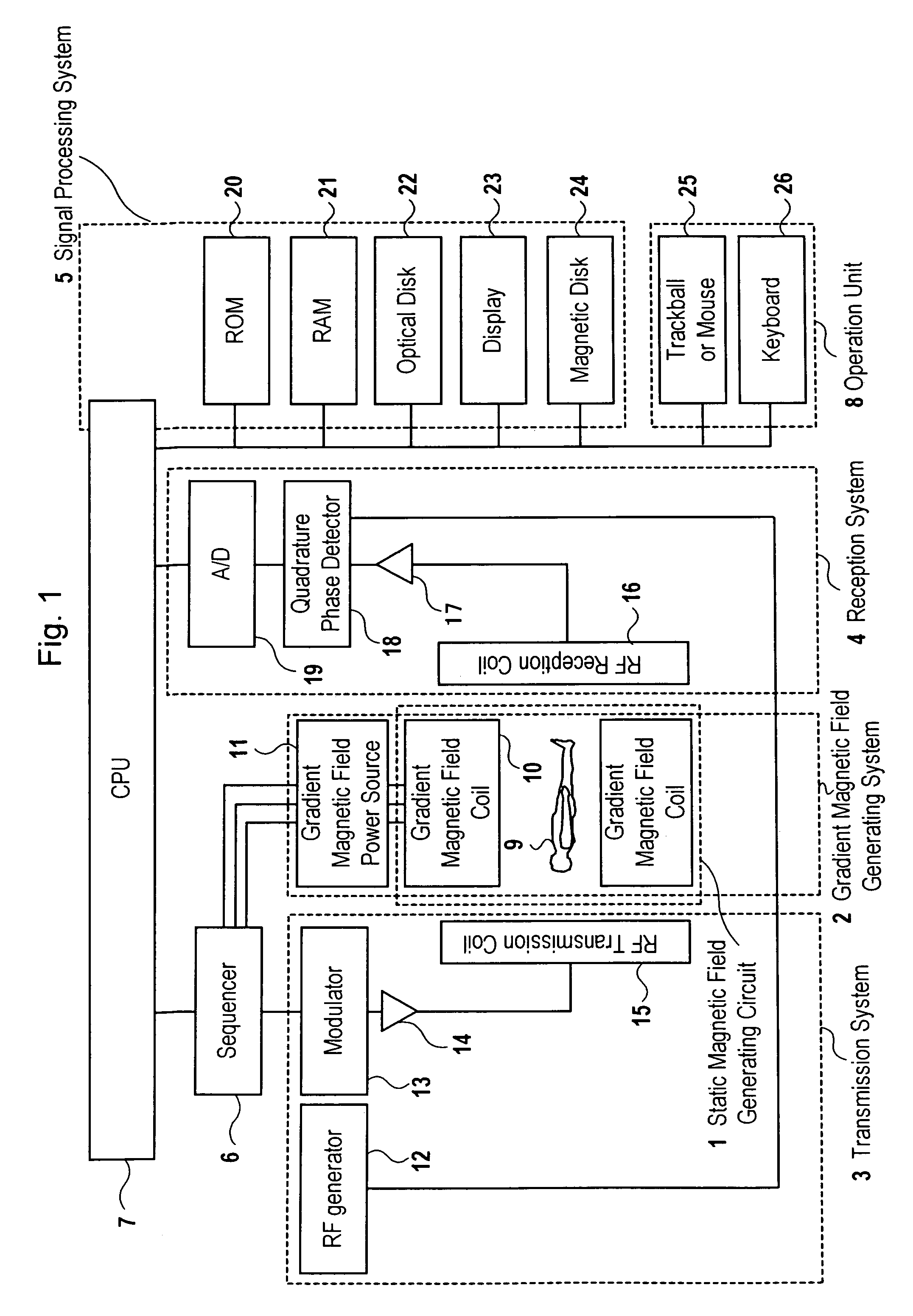
[0034]FIG. 1 is a block diagram showing a schematic structure of an MRI apparatus according to the invention. As shown in FIG. 1, the MRI apparatus includes static magnetic field generator 1, gradient magnetic field generating system 2, transmission system 3, reception system 4, signal processing system 5, sequencer 6, central processing unit (CPU) 7, and operation unit 8.

[0035]Static magnetic field generator 1 is designed to generate a uniform static magnetic field having a predetermined strength to a space of a predetermined size with which object 9 can be inserted in a longitudinal direction of the object or in a direction perpendicular thereto, including a permanent magnet, or a resistive magnet, or a superconductive magnet.

[0036]Gradient magnetic field generating system 2 includes gradient magnetic field coil 10 for generating gradient magnetic fields in X-, Y-, and Z-direct...


PUM


Abstract

In diffusion weighted imaging, motion monitoring navigation echoes are measured at every measurement of data after applying an RF excitation pulse, and one of them is set as a reference navigation echo. The reference navigation echo and other navigation echoes are one-dimensionally Fourier-transformed, a linear phase gradient thereof is calculated from those data, a linear phase gradient of the reference navigation echo is compared with those of other navigation echoes, and it is judged whether a difference therebetween is within an acceptable value or not. An echo signal corresponding to a navigation echo having the above difference being larger than the acceptable value is judged that correction based on the navigated motion correction is not applicable therein, and the image is produced by using an echo signal measured along with a navigation echo having the difference being the acceptable value or less. In this manner, a motion component included in the echo signal used for producing the image is made uniform and motion artifacts are eliminated.

Description

TECHNICAL FIELD[0001]The present invention relates to a magnetic resonance imaging method and a magnetic resonance imaging apparatus (hereinafter referred to as MRI apparatus) for obtaining an image in which body movement of an object to be examined is corrected by using a navigation echo, more particularly to an imaging method and apparatus suitable for obtaining a diffusion weighted image reflecting strength of Brownian motion of water molecule in the object's tissue on signal strength.BACKGROUND OF THE INVENTION[0002]An MRI apparatus is designed to generate a magnetic resonance imaging phenomenon to a nuclear spin in an object to be examined by applying a radio-frequency magnetic field on the object laid in a static magnetic field, measure a nuclear magnetic resonance signal generated inside the object, and process the signal to produce an image.[0003]Imaging techniques of the MRI apparatus include the spin echo method (SE method), a gradient echo method (GE method), an echo plan...

Claims


Application Information

Patent Timeline
Patent Type & Authority Patents(United States)
IPC IPC(8): G01V3/00G01R33/54A61B5/055G01R33/48G01R33/565G01R33/567
CPCA61B5/7257A61B5/7289G01R33/56341G01R33/56509G01R33/5616A61B5/055G01R33/5676
Inventor KUMAI, HIDEKIKAWASAKI, SHINJITAKEUCHI, HIROYUKI
Owner HITACHI MEDICAL CORP
Why Eureka
Try Eureka