Slide rail

a technology of sliding rails and sliding bars, which is applied in the field of sliding rails, can solve the problem that the drawing board cannot be easily pulled out, and achieve the effect of removing defects or drawbacks

Active Publication Date: 2007-02-20
THK CO LTD
View PDF16 Cites 6 Cited by
  • Summary
  • Abstract
  • Description
  • Claims
  • Application Information

AI Technical Summary

Benefits of technology

[0006]It is therefore an object of the present invention to substantially eliminate defects or drawbacks encountered in the prior art as mentioned above, and to provide a slide rail (unit) having a sliding locus of a drawer different from that of conventional structure having a linear sliding locus.
[0023]According to the structure of the slide rail unit mentioned above, the object to be pulled out, such as drawer for furniture, desk or like, can be pulled out along the circular-arc locus, not a conventional linear locus. Therefore, it becomes possible to attach the slide rail to the body in which the object is slidably accommodated in various ways, and for example, the drawer can be pulled out along the circular-arc locus in the vertical plane or in the horizontal plane, thus being advantageous.

Problems solved by technology

In such linear structure, when the drawer is pulled out linearly, there may cause a case that the drawer collides with an obstacle or the drawer cannot be easily pulled out, thus being inconvenient.

Method used


Image

  • Slide rail
  • Slide rail
  • Slide rail

Examples


first embodiment

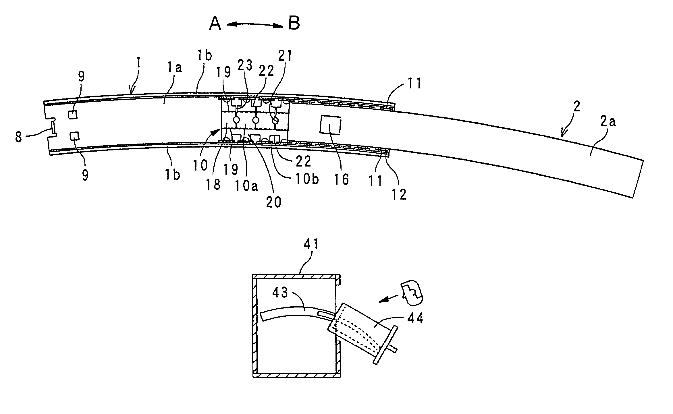
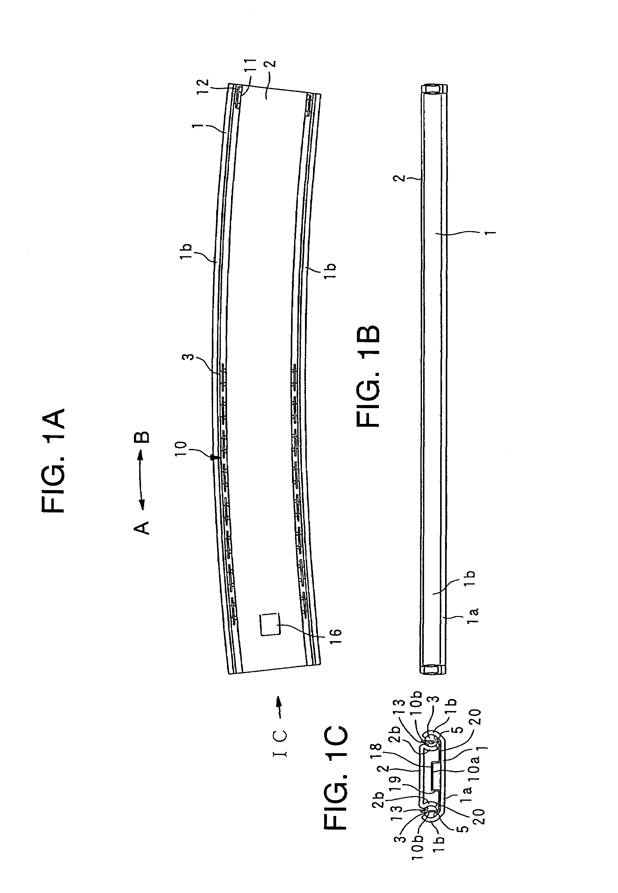
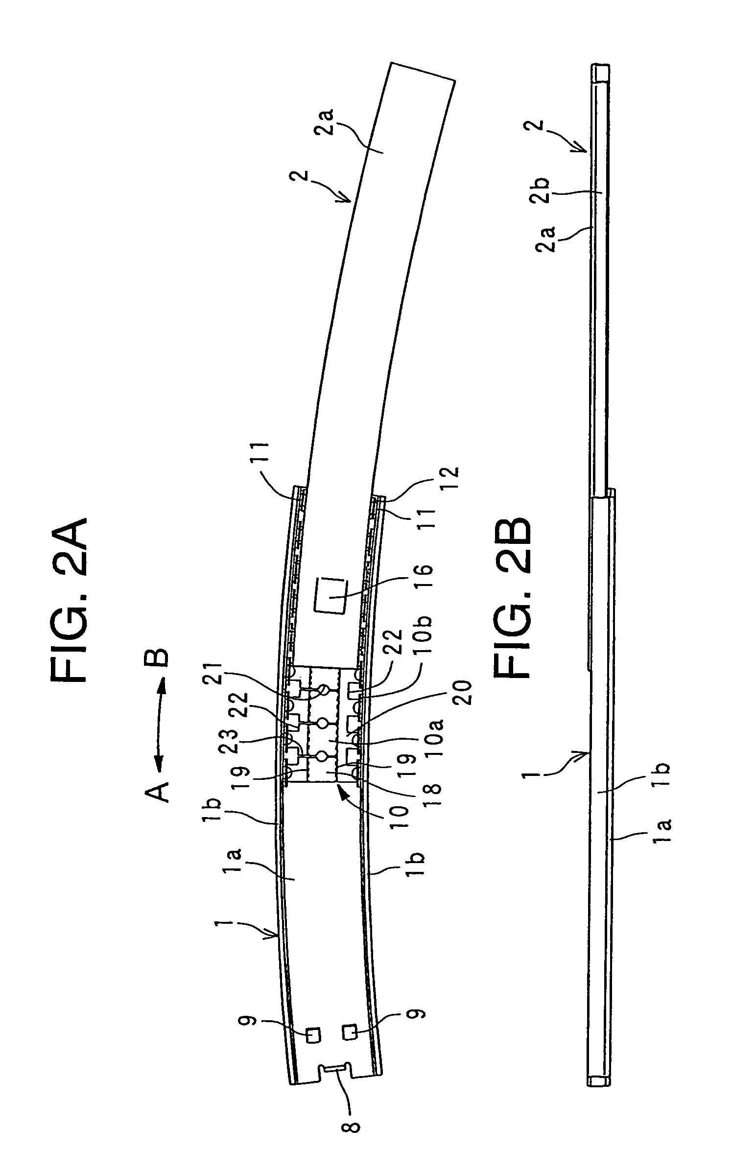
[0041]First, with reference to FIGS. 1 and 2 representing the present invention, a slide rail is generally a metal article for smoothly opening or closing an object to be pulled out, and for example, the slide rail is attached or mounted to a drawer or drawers of a system kitchen, a sink cabinet, a furniture such as chiffonier, dresser, system furniture or like. The slide rail (unit) includes an outer rail (member) 1, an inner rail (member) 2, and a number of balls 3 disposed between the outer and inner rails 1 and 2 so as to be capable of rolling therealong. FIG. 1 shows a state in which the inner rail 2 is accommodated and, on the other hand, FIG. 2 shows a state in which the inner rail 2 is pulled out.

[0042]The outer rail 1 has a channel-shaped cross section, and is composed of a bottom wall section 1a extending in a longitudinal direction, and a pair of side wall sections 1b bent at both sides in a short length (width) side direction of the bottom wall section 1a. Each of the pa...

second embodiment

[0057]FIGS. 3 and 4 show a slide rail according to the present invention. FIG. 3 shows the state in which the inner rail 2 is accommodated, and FIG. 4 shows the state in which the inner rail 2 is pulled out.

[0058]The second embodiment differs from the first embodiment in the curved structure of the outer and inner rails 1 and 2, and the other structures are substantially the same as those of the first embodiment, so that the like reference numerals are added to the corresponding portions, and explanations thereof are omitted herein. In this second embodiment, the outer rail 1 is bent in the circular-arc shape in a virtual plane perpendicular to the bottom wall section 1a of the outer rail 1 (i.e., in a plane shown in FIG. 3B (FIG. 4B)), and the inner rail 2 is also bent in the circular-arc shape having a constant radius of curvature in a virtual plane perpendicular to the bottom wall section 2a of the inner rail 2 (this bending state being called “belly or vertically bent form”). In...


PUM


Abstract

A slide rail unit for guiding an object to be pulled out, such as drawer, from a body, such as furniture or desk, in which the object is slidably accommodated includes a body side rail provided for the body, and an object (i.e., drawer) side rail provided for the object to be pulled out to be slidable relative to the body side rail. The body side rail and the object side rail each has a portion bent in a circular-arc shape so that the object is pulled out along a circular-arc locus.

Description

BACKGROUND OF THE INVENTION[0001]1. Field of the Invention[0002]The present invention relates to a slide rail (or slide rail unit) for smoothly guiding a pulling or drawing motion of an object, such as drawer, to be pulled out from a body structure such as furniture, desk or like.[0003]2. Related Art[0004]A slide rail (unit) is known as a member which is attached to, for example, a drawer of a furniture, desk or like so as to allow the drawer to be easily and smoothly opened or closed. Such slide rail is disclosed, for example, in Japanese Patent Laid-open (KOKAI) Publication No. SHO 51-048046. This Japanese Patent Laid-open (KOKAI) Publication No. SHO 51-048046 corresponds to DE 2540656, GB 1512069, and U.S. Pat. No. 3,966,273. The disclosure of U.S. Pat. No. 3,966,273 is incorporated by reference in its entirety The slide rail is generally composed of an outer rail (member) and an inner rail (member) which is fitted to the outer rail. A number of balls are disposed between these o...

Claims


Application Information

Patent Timeline
Patent Type & Authority Patents(United States)
IPC IPC(8): A47B88/04A47B88/48A47B88/60
CPCA47B88/06A47B88/04A47B88/48A47B46/00A47B83/045A47B88/443A47B88/40
Inventor HOSHIDE, KAORUSATO, AKIRAKOUCHI, MINORUSASAKI, SOICHI
Owner THK CO LTD
Why Eureka
Try Eureka