Hydraulic system for driving control rod drive mechanism

a hydraulic system and control rod technology, applied in nuclear engineering problems, nuclear elements, greenhouse gas reduction, etc., can solve the problems of high running cost, high initial cost deterioration of control rod drive water pump, so as to achieve suitable performance and eliminate defects or drawbacks

Inactive Publication Date: 2007-08-02
KK TOSHIBA
View PDF2 Cites 2 Cited by
  • Summary
  • Abstract
  • Description
  • Claims
  • Application Information

AI Technical Summary

Benefits of technology

[0015] Accordingly, an object of the present invention is to substantially eliminate defects or drawbacks encountered in the prior art mentioned above and to provide a hydraulic system for driving a control rod driving mechanism, which aims that a dedicated low-pressure pump for charging an HCU accumulator or a booster pump is used for handling all or a part of the water charging operation of charging the HCU accumulator of the hydraulic control unit with pressurized water for enabling the control rod drive water pump to maintain suitable performance for a long time, as well as relaxing the specifications required thereof such as high pump head.
[0016] Another object of the present invention is to provide a hydraulic system for driving a control rod drive mechanism capable of improving reliability, i.e., suppressing deterioration in the control rod drive water pump with advantages of reduced costs, reduced power consumption, and so forth.
[0017] A further object of the present invention is to provide a hydraulic system for driving a control rod drive mechanism capable of requiring no full-time operation of the control rod drive water pump at the high discharge pressure so as to suppress erosion occurring at various valves or orifices and charging HCU accumulator with water, which is used for driving the control rods in a sure manner after scram reset.
[0045] According to the present invention of the characters mentioned above, an additional pump is disposed for charging the HCU accumulator with water, independent of the control rod drive water pump. Note that a low-pressure dedicated pump or a booster pump is employed as the additional pump. With such an arrangement, the additional pump performs all or a part of the operation or function of charging the HCU accumulator of the hydraulic control unit with water. This enables the performance of the control rod drive water to be maintained for a long time and relaxes the high pump head specifications required thereof. Accordingly, a control rod drive water pump of the kind employed in BWR plants can be employed in the present invention. This improves reliability of the control rod drive water pump, i.e., suppresses deterioration in this pump. Furthermore, this reduces costs and power consumption.
[0046] Furthermore, with the system according to the present invention, the control rod drive water pump does not need to operate at the high discharge pressure at all times. This improves the useful life of the control rod drive water pump, as well as reducing costs thereof. Furthermore, the system according to the present invention may include the water lines with reduced maximum pressure specifications, except for the charging line, thereby reducing costs thereof.
[0047] In addition, the present invention has the advantages of: relaxation of the pressure-difference conditions for the CRD system flow control valve (conditions for suppressing erosion); relaxation of the pressure-difference conditions for the flow regulator / orifice of the RIP / CUW pump purge line; relaxation of the pressure-difference conditions for the control rod drive water pump mini flow line orifice; relaxation of the pressure-difference conditions for the control rod drive water pump mini flow line manual needle valve (conditions for suppressing erosion); and operation of the control rod drive mechanism with reduced driving force, thereby allowing the costs of the system to be further reduced.

Problems solved by technology

Accordingly, long-time operation of conventional ABWR plants leads to a problem of deterioration in the control rod drive water pump.
Accordingly, the initial cost of the ABWR control rod drive water pump is higher than that of a BWR plant control rod drive water pump.
Furthermore, such an ABWR control rod drive water pump requires great electric power, also leading to a problem of high running cost.
Furthermore, with conventional arrangements, the high discharge pressure of the control rod drive water pump causes great difference in pressure at a CRD system flow control valve, flow regulator / orifice of the RIP / CUW pump purge line, control rod drive water pump mini flow line orifice or control rod drive water pump mini flow line manual needle valve, and the like, also leading to a problem of erosion thereof in some cases.

Method used


Image

  • Hydraulic system for driving control rod drive mechanism
  • Hydraulic system for driving control rod drive mechanism
  • Hydraulic system for driving control rod drive mechanism

Examples


first embodiment

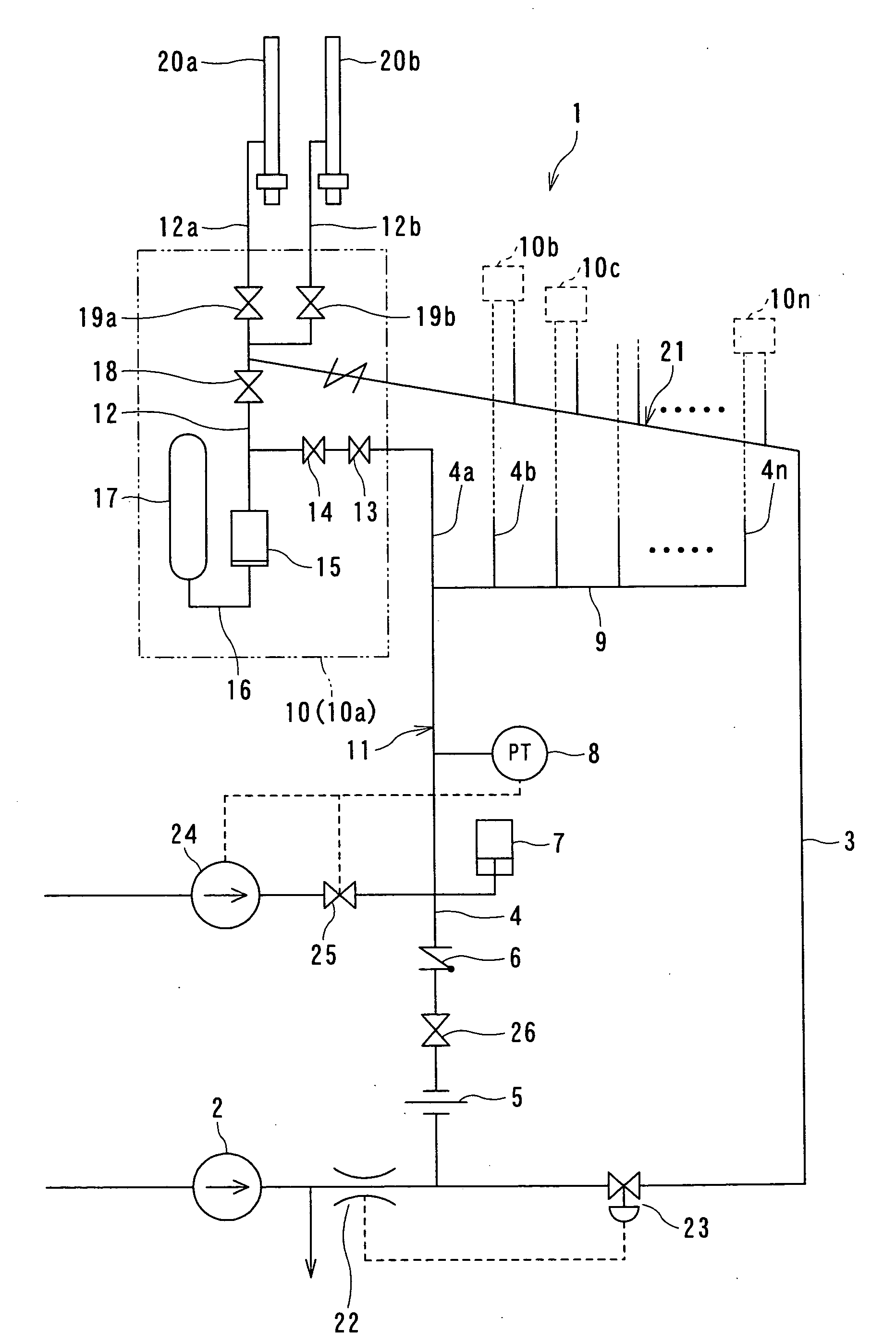
[0055]FIG. 1 is a block diagram showing a configuration of a control rod drive hydraulic system according to a first embodiment of the present invention.

[0056] Referring to FIG. 1, a control rod drive hydraulic system 1 includes a control rod drive water pump 2 having a discharge port which is branched to a purge water line 3 for supplying cooling water to a control rod drive mechanism and a charging water line 4 for supplying water to an HCU accumulator so as to charge the HCU accumulator with water. The charging water line 4 is connected to a charging header 9 with an orifice 5, a check valve 6, an accumulator 7 and a pressure gauge 8, provided in that order at suitable positions on the way of the line 4.

[0057] Multiple charging line branch pipes 4a, 4b, . . . , 4n are connected to the charging header 9. Each of the charging line branch pipes 4a, 4b, . . . , 4n is connected to each of hydraulic control units (HCU) 10 (10a, 10b, ---, 10n) to thereby form a charging line 11.

[0058...

second embodiment

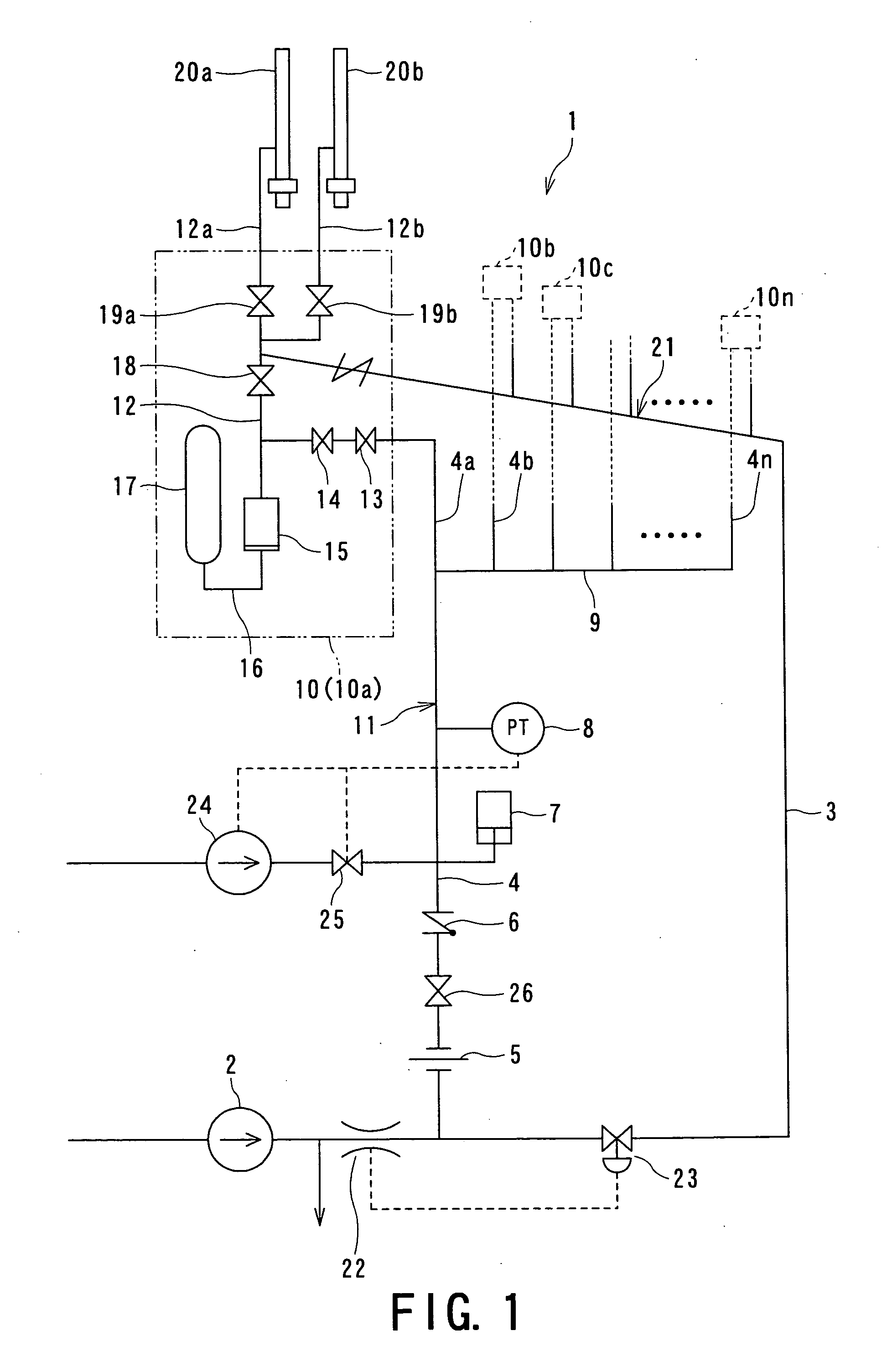
[0072]FIG. 2 is a block diagram which shows a configuration of a control rod drive hydraulic system according to a second embodiment of the present invention.

[0073] As shown in FIG. 2, the control rod drive hydraulic system 1 according to this embodiment has a configuration, different from that of FIG. 1, in which the charging line 11 includes the charging pump 24. The charging pump 24 operates along with the control rod drive water pump 2, thereby charging the HCU accumulator 15 at a necessary pressure.

[0074] That is, the charging pump 24, serving as a booster pump for charging the HCU accumulator, is provided to the charging line 11 in series with the control rod drive water pump 2. The charging pump 24 has pump head of 5 to 7 MPa or more, for example.

[0075] Furthermore, the charging line 11 includes a bypass line 27 in parallel with the charging pump 24. With such an arrangement, a bypass valve 27a is opened until the pressure drops to a predetermined value at which the contro...

third embodiment

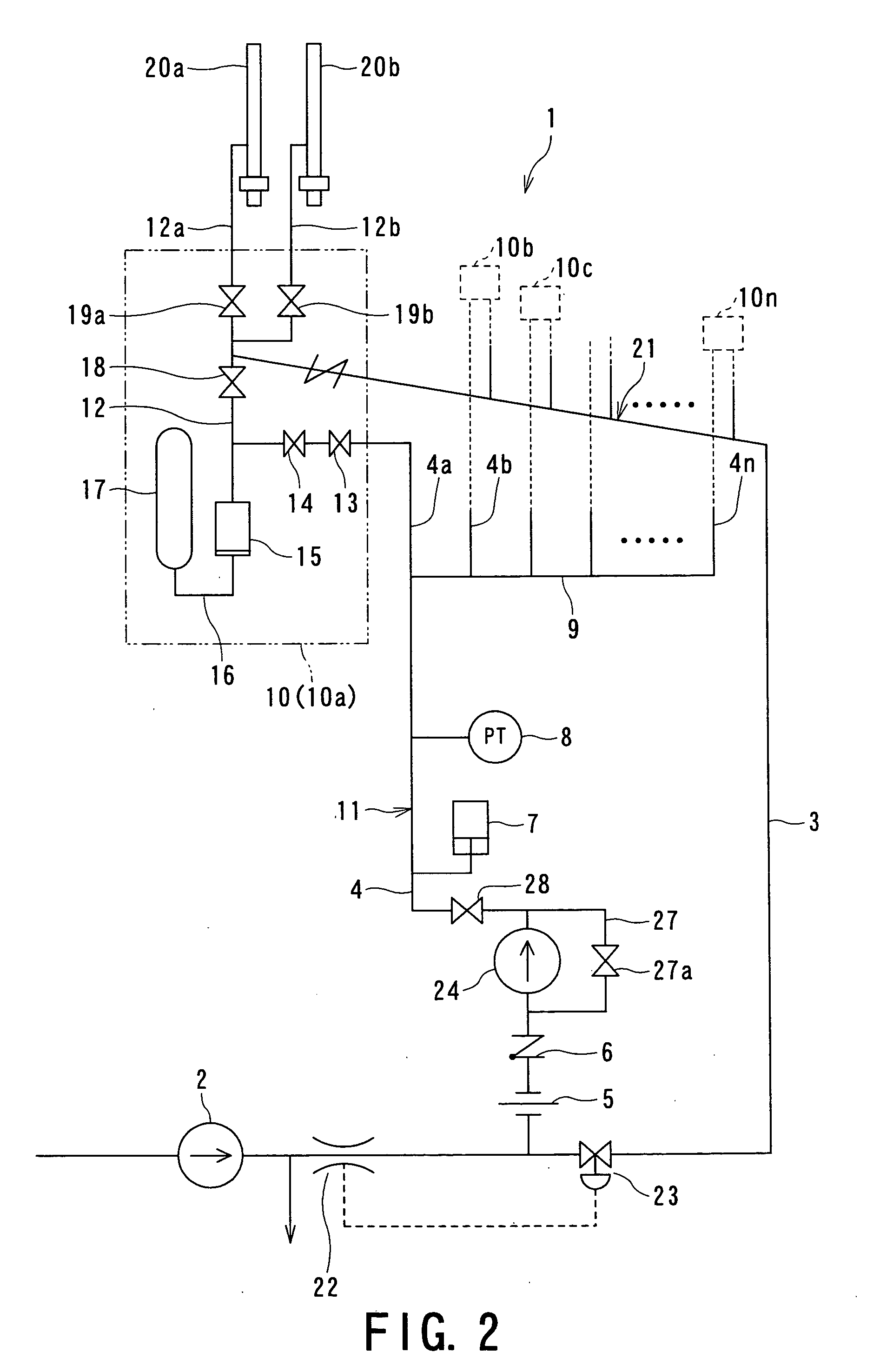
[0087]FIG. 3 is a block diagram which shows a configuration of a control rod drive hydraulic system according to a third embodiment of the present invention.

[0088] As shown in FIG. 3, the control rod drive hydraulic system 1 includes the cooling water line 21 having the control rod drive water pump 2 and the charging line 11 having the charging pump 24 for scram, independent of each other.

[0089] That is, the charging line 11 includes the charging pump 24 having a function of charging the HCU accumulator 15 with water at a necessary pressure independently. The charging line 11, including the charging pump 24, is provided, independent of the cooling water line 21, which has the control rod drive water pump 2.

[0090] Furthermore, with regard to the charging line 11 according to this third embodiment, the pressure gauge 8 is also provided downstream of the charging pump 24. The pressure at which the HCU accumulator 15 is charged with water is monitored with the pressure gauge 8. The h...


PUM


Abstract

A hydraulic system for driving a control rod drive mechanism includes a control rod drive water pump, a charging line connected to a discharge side of the control rod drive water pump and including a pressure gauge on the discharge side thereof, a purge line connected to the discharge side of the control rod drive water pump for feeding a coolant to a control rod drive mechanism, and a plurality of hydraulic control units connected to the charging line through charging headers and the purge line, each of said hydraulic control units including an accumulator for storing pressurized water using high-pressure gas and a scrum valve through which the accumulator is connected to the control rod drive mechanism. A charging pump is further connected to the charging line so as to independently charge the accumulators with water at a predetermined pressure.

Description

BACKGROUND OF THE INVENTION [0001] 1. Field of the Invention [0002] The present invention relates to a control rod drive hydraulic system for driving a control rod drive mechanism of an advanced boiling water reactor (ABWR) so as to perform emergency insertion of control rods (i.e. scram) by hydraulic pressure, and particularly, to a hydraulic system for driving control rod mechanism (which may be called hereafter “control rod drive hydraulic system”) including a pumping system having an improved configuration serving as a pressurizing source for pressurizing water for driving the control rods. [0003] 2. Related Art [0004] The ABWR employs a fine motion control rod drive mechanism (FMCRD: which will simply be referred to as “control rod drive mechanism” hereafter) for controlling insertion / withdrawal of control rods. This enables power (output) control of a reactor and functions thereof such as operation, shutdown, and so forth. [0005] The control rod drive mechanism has two types o...

Claims


Application Information

Patent Timeline
Patent Type & Authority Applications(United States)
IPC IPC(8): G21C7/06
CPCG21C7/16G21Y2002/206Y02E30/39G21Y2002/304G21Y2004/30G21Y2002/301Y02E30/30
Inventor USUI, HIDEKAZUISHIBASHI, FUMIHIKO
Owner KK TOSHIBA
Why Eureka
Try Eureka