Video image display device and video image display method

a video image and display device technology, applied in the field of video image display devices and video image display methods, can solve the problems of excessive expansion of video image data of the next scene, deterioration of image quality, and expansion of luminance ranges

Inactive Publication Date: 2007-12-13
SEIKO EPSON CORP
View PDF4 Cites 28 Cited by
  • Summary
  • Abstract
  • Description
  • Claims
  • Application Information

AI Technical Summary

Benefits of technology

[0011] According to the above aspect of the invention, the expansion factor deriving unit outputs an ideal expansion factor of the present frame suitable for a new scene when the scene-chance is detected; outputs a first modified expansion factor of the present frame obtained by modifying the ideal, expansion factor of the present frame in accordance with a predetermined first expansion factor modification rule when the scene-change is not detected and the change into the black screen state is not detected; and outputs a second modified expansion factor of the present frame obtained by modifying the ideal expansion factor of the present frame to a value smaller than the first modified expansion factor of the present frame in accordance with a predetermined second expansion factor modification rule when the scene-change is not detected and the change to the black screen state is detected. Accordingly, in the case of the scene-change where the scene fades out from a previous scene to change into the black screen and the black screen fades into a next scene, it is possible to suppress the abrupt change of the expansion factor from the previous frame, thereby making it possible to perform the luminance range expansion process suitably for the new scene.
[0045] According to this arrangement, it is possible to easily detect the change into the dark screen state and the change into the black screen state.

Problems solved by technology

However, according to the luminance range expansion process known in the art, since the luminance range expansion process is performed to the video image data without consideration of an abrupt change of the image (i.e., luminance of the image) between frames, there is a possibility that the image quality is deteriorated by the luminance range expansion process.
When the luminance expansion rate increases, the video image data of the next scene is excessively expanded.
Therefore, there is a possibility of causing deterioration of the image quality known as halation.
Moreover, according to the lighting control process known in the art, since the lighting control process is performed without consideration of the scene-change, there is a possibility that the lighting control process deteriorates the image quality.

Method used


Image

  • Video image display device and video image display method
  • Video image display device and video image display method
  • Video image display device and video image display method

Examples


first embodiment

A.

A1. Structure of Device:

A2. Processes of Image Characterizing Quality Calculating Unit:

A3. Processes of Expansion Factor Deriving Unit And Expansion Factor Output Mode Determining Unit:

A4. Processes of Lighting Factor Deriving Unit And Lighting Factor Output Mode Determining Unit:

A5. Derivation of Expansion Factor:

A6. Luminance Range Expansion Process:

A7. Derivation of Lighting Factor:

A8. Lighting Control Process:

A9. Advantage of Embodiment:

B. Second Embodiment:

C. Other Embodiments:

A. First Embodiment

A1. Structure of Device

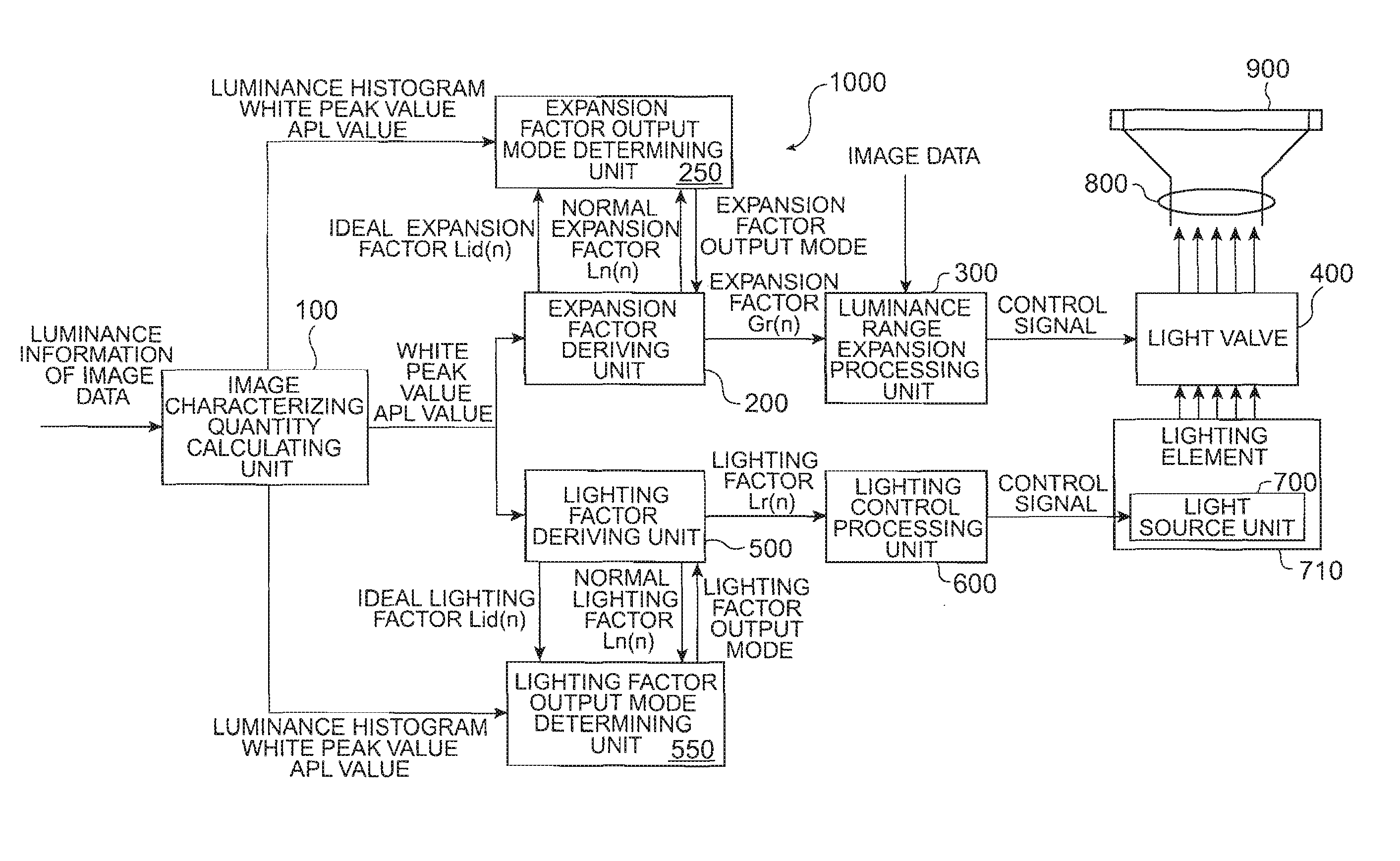
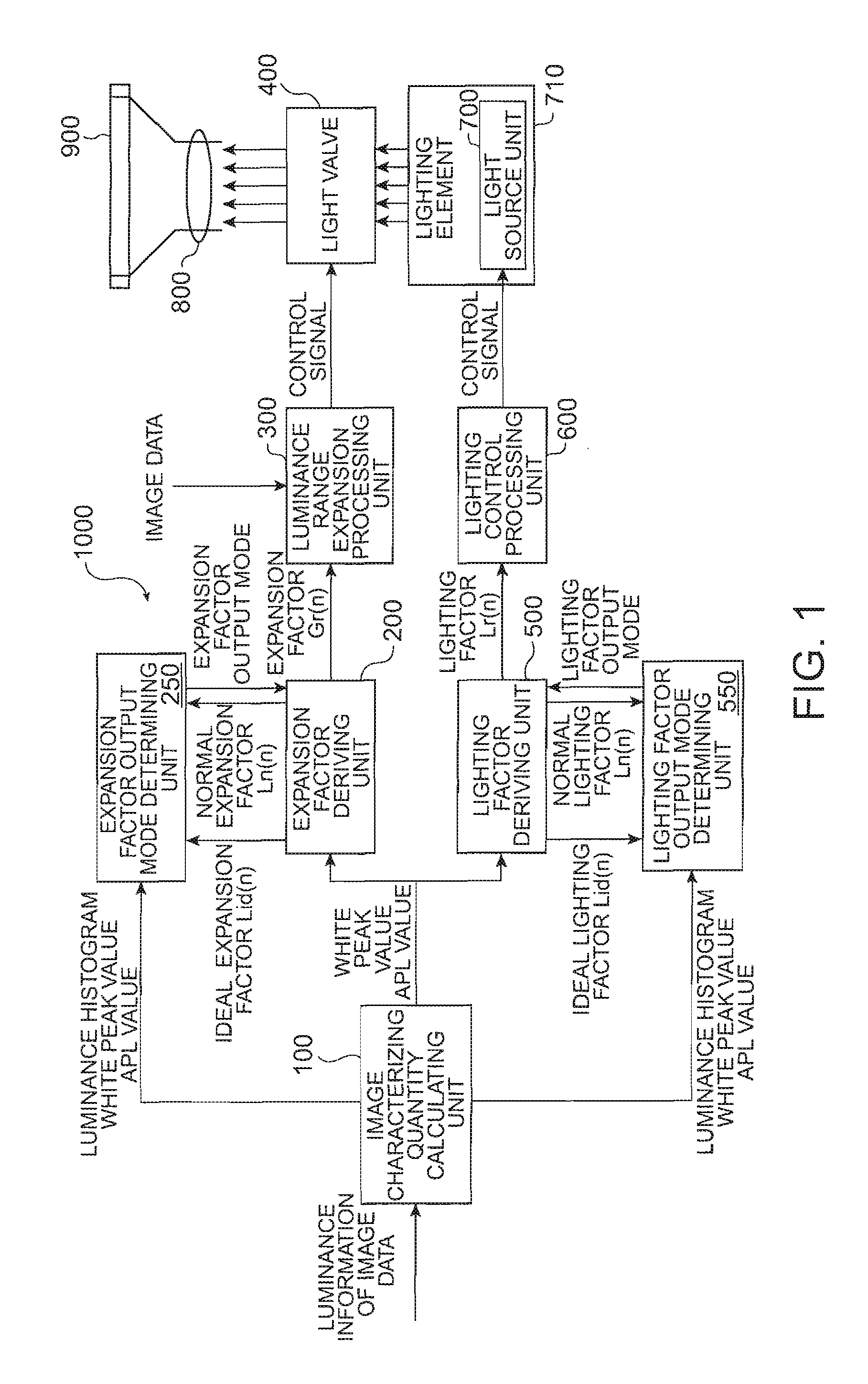
[0074]FIG. 1 is a schematic block diagram showing a functional structure of a video image display device 1000 according to a first embodiment of the invention. The video image display device 1000 has a function of performing a luminance range expansion process for expanding a luminance range of image data in one frame of video image data and performing a lighting control process of a light source unit 710, on the basis of an image charact...

second embodiment

B. Second Embodiment

[0200] The structure of a second embodiment of the invention is the same as the first embodiment, except that the method of calculating the modified normal variation dWGn(n) and the modified black screen variation dWGs(n) in step S1300 of FIG. 11 is different from each other. In the second embodiment, the modified normal variation dWGn(n) and the modified black screen variation dWGs(n) are obtained by multiplying variations dWGn1(n) and dWGs1(n) with the modification factor ScaleG(n), as represented by Formulae 21 and 22.

dWGn(n)=dWGn1(n)*ScaleG(n)  [Formula 21]

dWGs(n)=dWGs1(n)*ScaleG(n)  [Formula 22]

[0201]FIG. 20 is a flowchart showing a sequence of processes for deriving the modified normal variation dWGn(n) and the modified black screen variation dWGs(n) according to the second embodiment of the invention. First, the expansion factor calculator 210 calculates the modified normal variation dWGn(n) and the modified black screen variation dWGs(n) in accordance wi...


PUM


Abstract

A video image display device is provided. The device includes an expansion factor deriving unit deriving and outputting an expansion factor for each frame of the video image data, for use in a luminance range expansion process for expanding a luminance range of the video image data on the basis of an image characterizing quantity related to the luminance of the video image data corresponding to the frame; a luminance range expansion processing unit performing the luminance range expansion process to the video image data on the basis of the expansion factor output from the expansion factor deriving unit; and a scene-change detecting unit detecting a change in a screen state of a present frame into a black screen state on the basis of the video image data and detecting a scene-change indicating that the scene of the video image has changed.

Description

BACKGROUND [0001] 1. Technical Field [0002] The present invention relates to a technique for displaying video images on the basis of video image data. [0003] 2. Related Art [0004] In a video image display device such as projectors, there have been proposed techniques for performing a luminance range expansion process for expanding a luminance range of image data in one frame of video image data, thereby improving a sense of contrast of the image. [0005] In addition, in a video image display device such as projectors equipped with an illumination device, there have been proposed techniques for performing a lighting control process for adjusting the luminance of the image, thereby improving image quality. Examples of the related art include JP-A-2001-343957, JP-A-2004-45634 and Japanese Patent No. 3308234. [0006] However, according to the luminance range expansion process known in the art, since the luminance range expansion process is performed to the video image data without conside...

Claims


Application Information

Patent Timeline
Patent Type & Authority Applications(United States)
IPC IPC(8): H04N9/74H04N5/57
CPCH04N5/147H04N5/20H04N5/57H04N21/44008H04N9/3155H04N9/3179H04N21/4318H04N5/7416
Inventor NOBORI, TATSUHIKO
Owner SEIKO EPSON CORP
Why Eureka
Try Eureka