

Device and method for adjusting parallax, imaging apparatus, and image reproduction device
- Summary
- Abstract
- Description
- Claims
- Application Information
AI Technical Summary
Benefits of technology
Problems solved by technology
Method used
Image

Examples
first embodiment
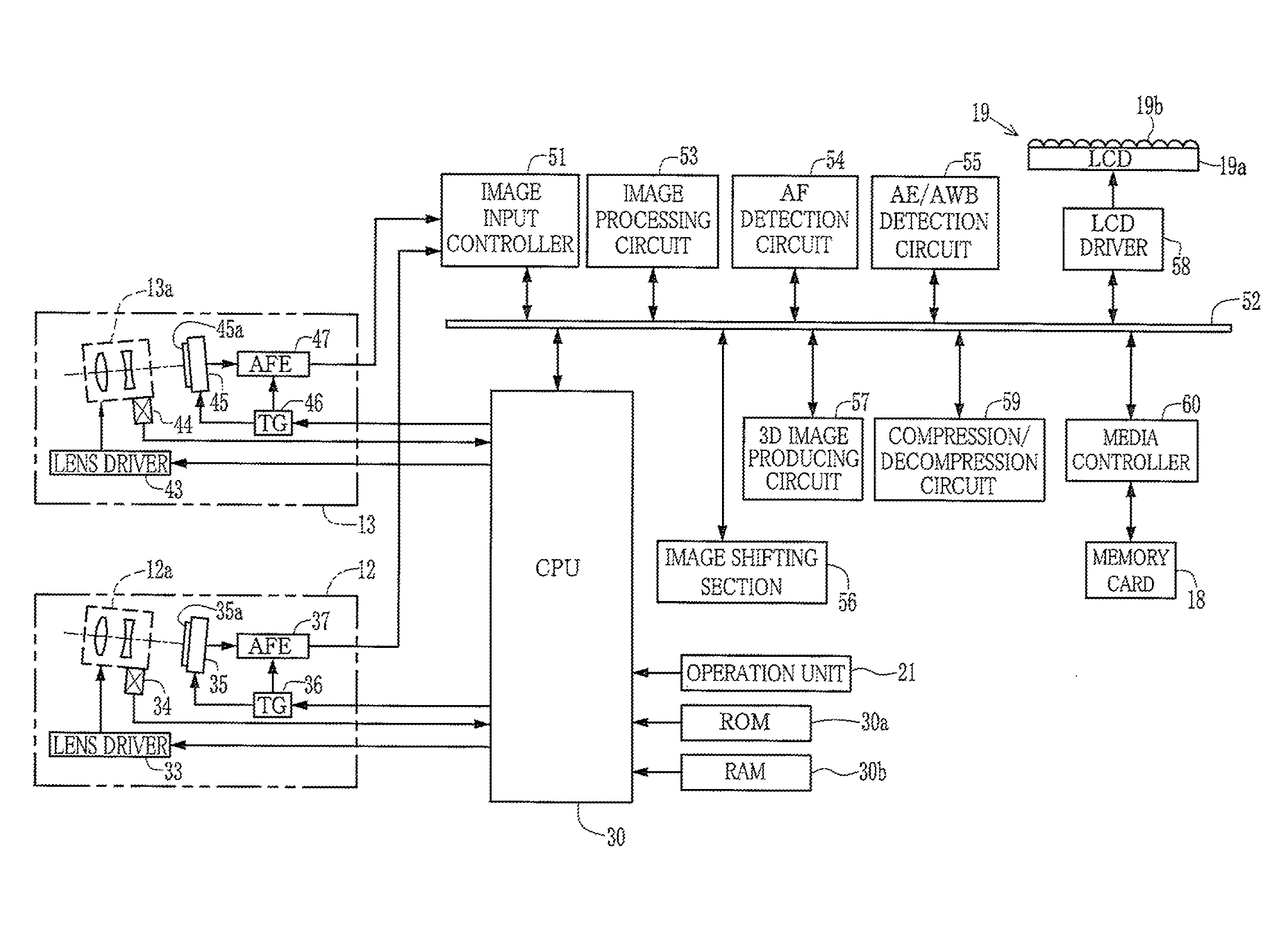
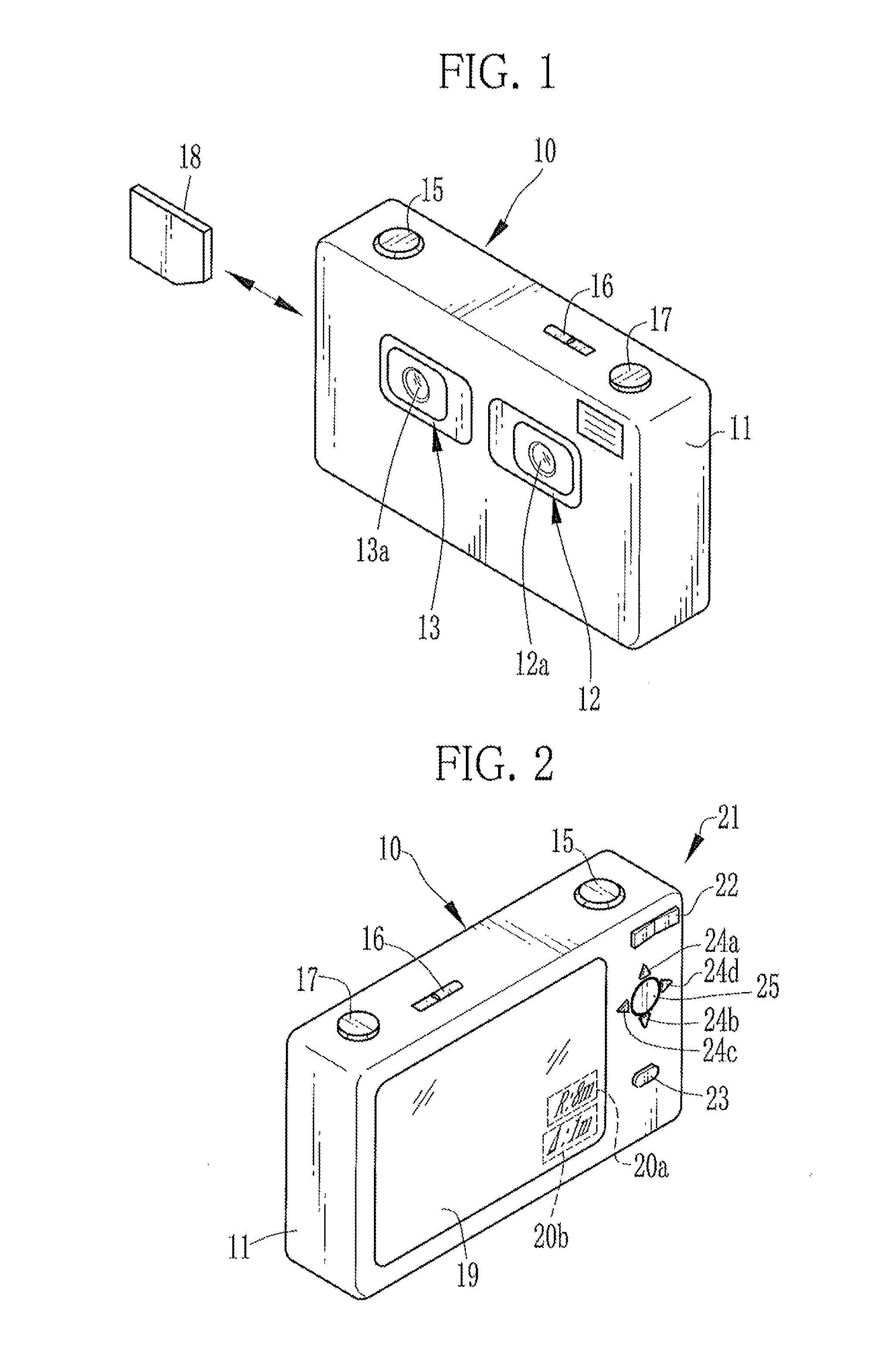
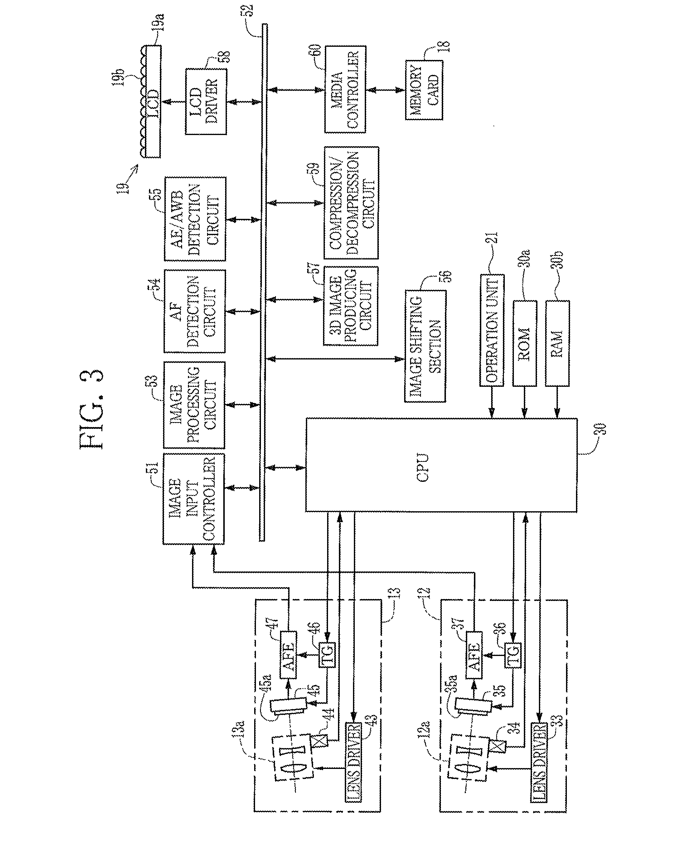
[0037]In FIGS. 1 and 2, a 3D digital camera (hereinafter referred to as the 3D camera) 10 comprises a camera body 11, left and right imaging systems 12 and 13 on the front of the camera body 11, a taking lens 12a of the left imaging system 12, and a taking lens 13a of the right imaging system 13. The left imaging system 12 captures a left viewpoint image. The right imaging system 13 captures a right viewpoint image. The left viewpoint image and the right viewpoint image constitute a parallax image.
[0038]The taking lenses 12a and 13a are spaced apart by a predetermined distance in a left-right direction. Each of the taking lenses 12a and 13a is a zoom lens and changes a focal length between a telephoto end and a wide-angle end.
[0039]A shutter release button 15, a power switch 16, and a mode dial 17 are disposed on a top face of the camera body 11. A card slot (not shown) is provided on the side of the camera body 11. A memory card 18 is inserted into the card slot in a detachable man...
second embodiment
[0099]In a second embodiment shown in FIGS. 7 and 8, the convergence point distance is changed by the distance proportionate to the operation amount and the shift amount of each viewpoint image is increased or reduced by a unit of pixel. Note that parts other than those described below are the same as those in the first embodiment, and the like parts have like numerals and descriptions thereof are omitted.
[0100]As shown in FIG. 7, the CPU 30 functions as the distance determining section 62, the shift amount setting section 63, and a shift amount increasing / reducing section 65. The up key 24a and the down key 24b constitute a first operation unit. A left key 24c and a right key 24d constitute a second operation unit. For example, the pressing operation of the left key 24c corresponds to the increasing operation for increasing the shift amount. The pressing operation of the right key 24d corresponds to the reducing operation for reducing the shift amount. A second operation signal tha...
third embodiment
[0108]In a third embodiment, the operation of the operation unit is switched, based on the focal length of the taking lens, between an operation for changing the convergence point distance and an operation for changing the shift amount by a unit of pixel. Note that parts other than those described are the same as those in the second embodiment, and like parts have like numerals and descriptions thereof are omitted.
[0109]As shown in FIG. 9, the CPU 30 functions as the distance determining section 62, the shift amount setting section 63, the shift amount increasing / reducing section 65, and an input controller 66. The up key 24a and the down key 24b are used as the first operation unit. The first operation unit is used for the distance determining section 62 and the shift amount increasing / reducing section 65. The focal length of the taking lens 12a is inputted from the lens sensor section 34, being a focal length obtaining section, to the input controller 66. Note that the focal lengt...
PUM
 Abstract
Description
Claims
Application Information