
Shut-off valve and method of shutting off opening of vacuum chamber

a technology of shut-off valve and vacuum chamber, which is applied in the direction of mechanical equipment, pile separation, transportation and packaging, etc., to achieve the effect of high sealing performan

Inactive Publication Date: 2005-11-10
ONODERA KOICHI
View PDF5 Cites 2 Cited by
  • Summary
  • Abstract
  • Description
  • Claims
  • Application Information

AI Technical Summary

Benefits of technology

[0007] An object of the present invention is therefore to substantially eliminate defects or drawbacks encountered in the prior art mentioned above and to provide an shut-off valve free of occurrence of particle with high sealing performance being maintained for a long time.
[0023] an air in the sealed space is sucked to thereby reduce a pressure in the sealed space and attract the sheet member towards the central axis of the shaft against the urging force of the urging member, thereby separating the sheet member closing the opening from the closed state thereof to open the same.
[0030] According to the invention of the structures and characters mentioned above, the rubbing between the sheet member of the valve opening / closing mechanism and the casing of the shut-off valve can be effectively prevented from causing, and accordingly, even in the mounting of an O-ring or like to the end surface of the sheet member, the sheet member be never worn, whereby substantially no particle is generated and an improved sealing performance can be maintained for a long period.

Problems solved by technology

However, with such shut-off valve, the O-ring is rubbed against the inner surface of a casing of the vacuum device every time the valve body rotates, which may cause, so-called, particle, thus being inconvenient.

Method used


Image

  • Shut-off valve and method of shutting off opening of vacuum chamber
  • Shut-off valve and method of shutting off opening of vacuum chamber
  • Shut-off valve and method of shutting off opening of vacuum chamber

Examples


Embodiment Construction

[0045] Preferred embodiments of a shut-off (open / close) valve according to the present invention will be described hereunder.

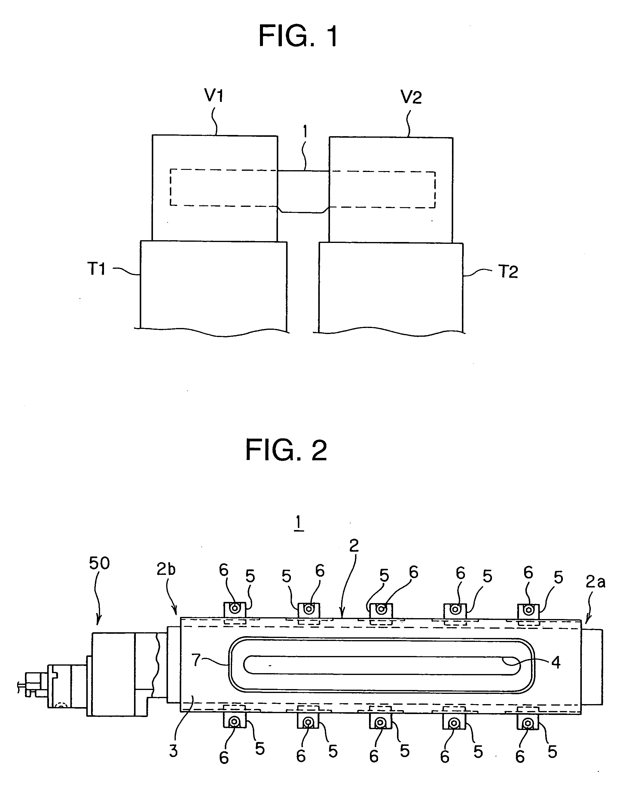
[0046] First, with reference to FIG. 1, an shut-off valve 1 is arranged between a lateral pair of vacuum chambers V (V1 and V2) mounted on tables T (T1 and T2), respectively, and a driving mechanism 50 (FIG. 2) of the shut-off valve 1 so as to project horizontally of the vacuum chambers V. The vacuum chambers V1 and V2 are provided with openings opposing to each other. The horizontally projecting arrangement of the driving mechanism 50 contributes easy maintenance thereof.

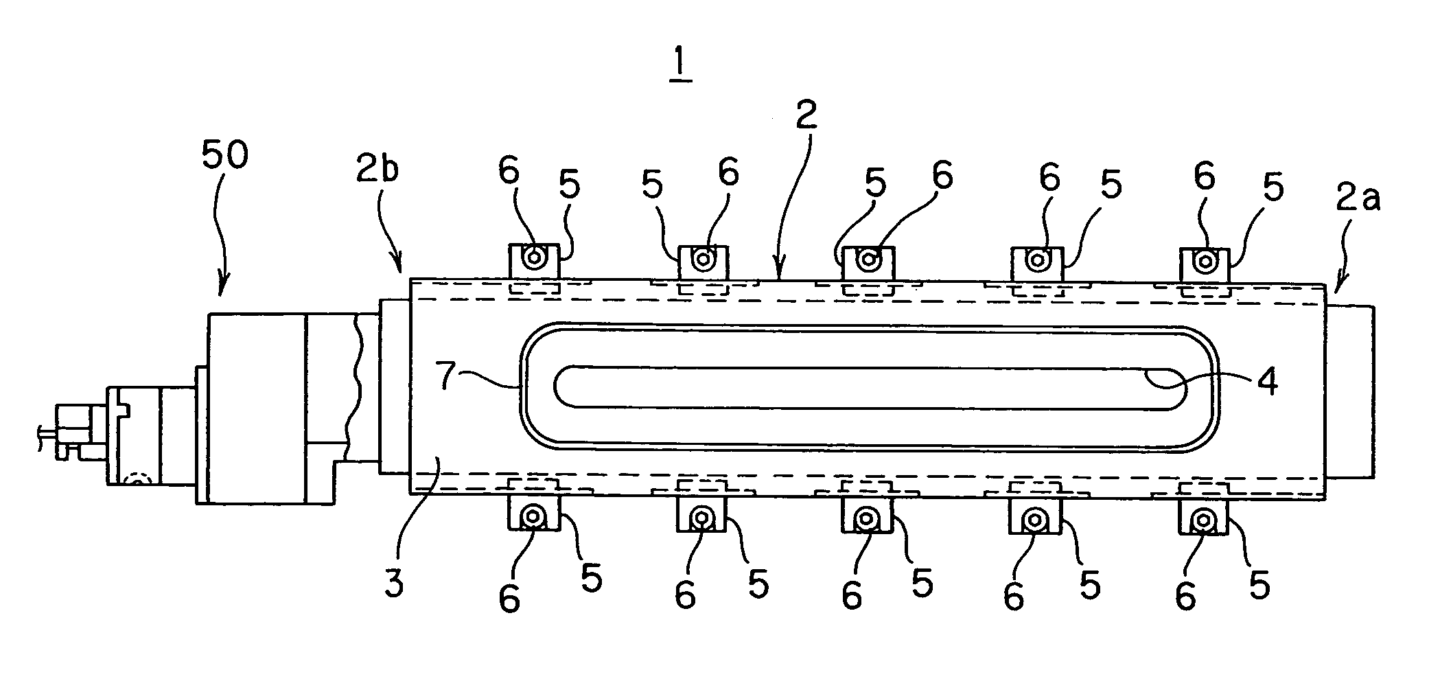
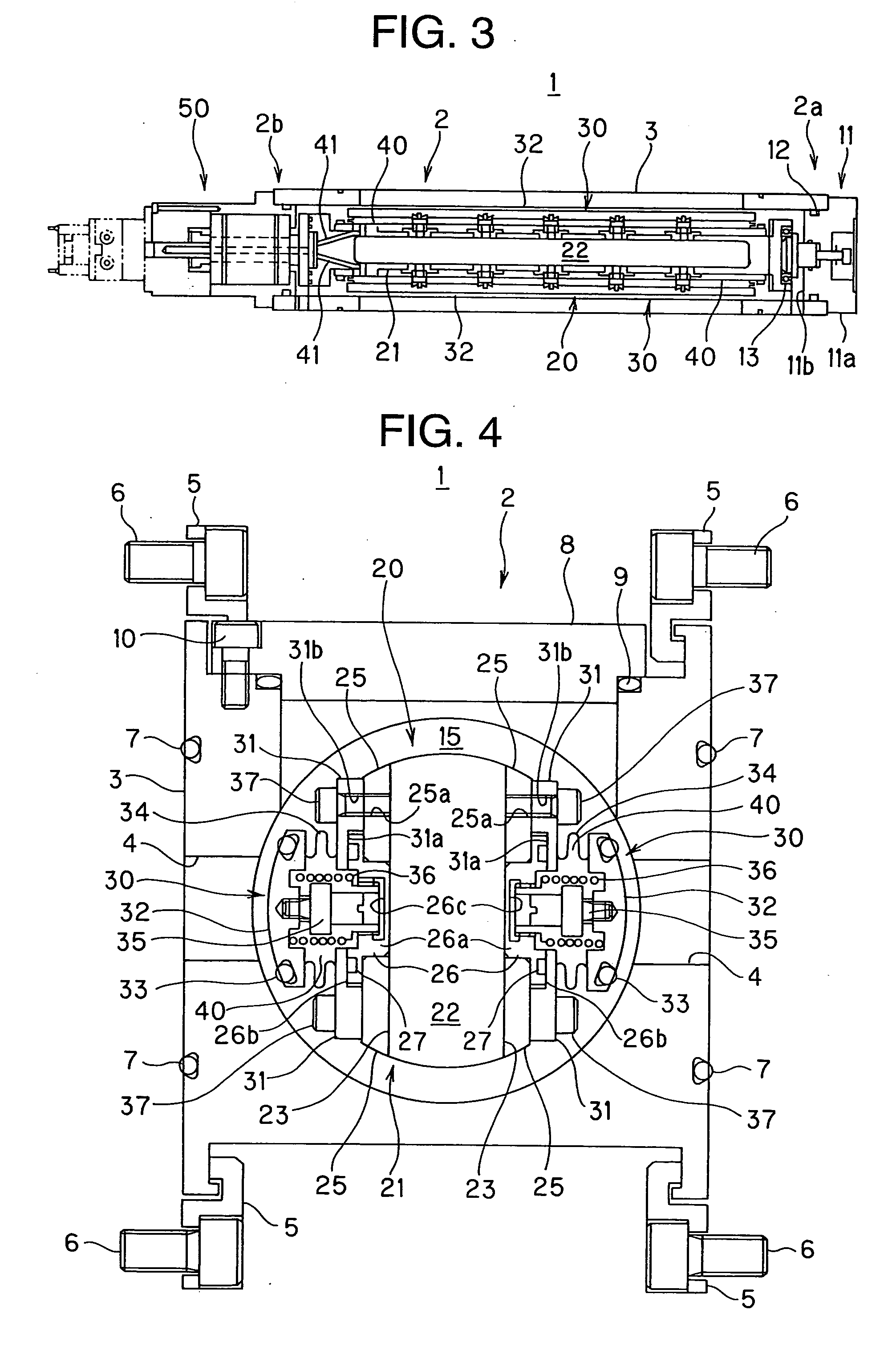
[0047] Next, referring to FIGS. 2 to 4, the shut-off valve 1 comprises a casing 2 having substantially a rectangular shape, a spool body (i.e., valve body) 20 arranged inside the casing 2 and a driving mechanism or section 50 mounted to an axial one end portion of the casing 2 and adapted to drive the spool body 20.

[0048] The casing 2, on the other hand, includes a casing body 3 having an ...


PUM


Abstract

A shut-off valve disposed between openings formed to a vacuum chamber includes a casing, a valve body disposed inside the casing and having a shaft rotating around a central axis of the valve body, a drive unit for driving the valve body to rotate the shaft, and an open / close mechanism provided for the shaft for opening and closing each of the openings. The open / close mechanism includes a sheet member mounted to the shaft so as to protrude outward in a radial direction of the shaft to thereby close each of the openings, an urging member urging the sheet member inward or outward in the radial direction of the shaft, and a seal member connected to the sheet member so as to be associated therewith and forming a sealed space between the sheet member and the shaft, which is formed with an air passage communicating with the sealed space.

Description

BACKGROUND OF THE INVENTION [0001] 1. Field of the Invention [0002] The present invention relates to a shut-off (open / close) valve for shutting off (opening and closing) openings formed to a vacuum chamber and also relates to a method of shutting off the openings by using such shut-off valve. [0003] 2. Related Art [0004] A shut-off valve provided for opening or closing a vacuum chamber of a vacuum device such as semiconductor manufacturing device has been variously studied and developed, and the inventor of the subject application had already provided such shut-off valve as disclosed, for example, in Japanese Patent Laid-Open (KOKAI) Publication No. HEI 11-351448. [0005] The shut-off valve disclosed in this publication is arranged horizontally between lateral vacuum chambers. This shut-off valve comprises a valve seat having lateral communication openings, a valve body which is arranged to be rotatable and movable in an axial direction of the valve seat and a driving mechanism for r...

Claims


Application Information

Patent Timeline
IPC IPC(8): B65H9/16F16K3/18F16K1/24F16K5/04F16K51/02
CPCF16K51/02F16K1/24H01L21/02
Inventor SHIGETAKA, KENJIRO
Owner ONODERA KOICHI
Learn More