Case holding mechanism

a technology of holding mechanism and case, which is applied in the direction of machine supports, hoisting equipment, washstands, etc., can solve the problems of inconvenient and disadvantageous, loosening of the engaged portion, etc., and achieve the effect of eliminating defects or drawbacks

Inactive Publication Date: 2006-10-26
TOYO ROKI MFG CO LTD
View PDF9 Cites 1 Cited by
  • Summary
  • Abstract
  • Description
  • Claims
  • Application Information

AI Technical Summary

Benefits of technology

[0009] Therefore, the present invention was conceived to substantially eliminate defects or drawbacks encountered in the prior art mentioned above and an object of the present invention is to provide a case holding mechanism capable of mounting the case in at least two directions firmly for a long time.

Problems solved by technology

However, in the holding mechanism of the Reference 1, the engagement is performed by utilizing the tapered structure, so that after the mounting, there is a fear for the engaged portion to be loosened in lapse of time, thus being inconvenient and disadvantageous.

Method used


Image

  • Case holding mechanism
  • Case holding mechanism
  • Case holding mechanism

Examples


Embodiment Construction

[0034] A preferred embodiment of the present invention will be described hereunder with reference to the accompanying drawings. In the following descriptions, terms of “upper”, “lower”, “right”, “left” and the like terms are used with reference to the illustration on the drawings or generally usable state of a canister.

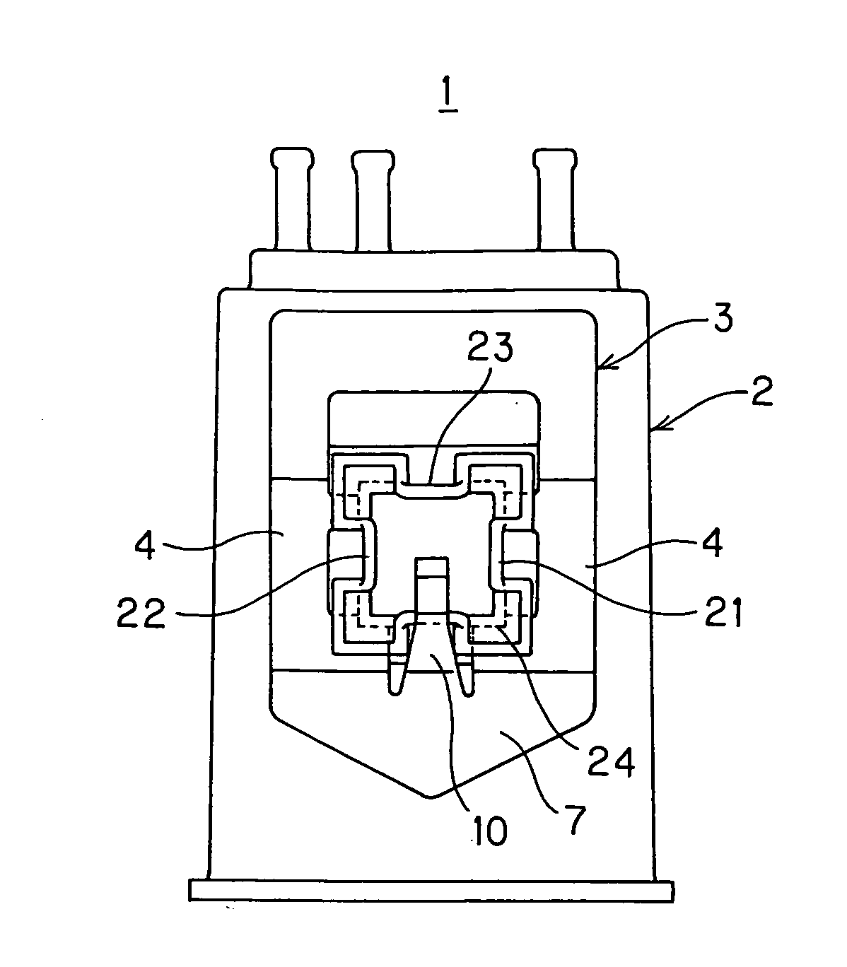
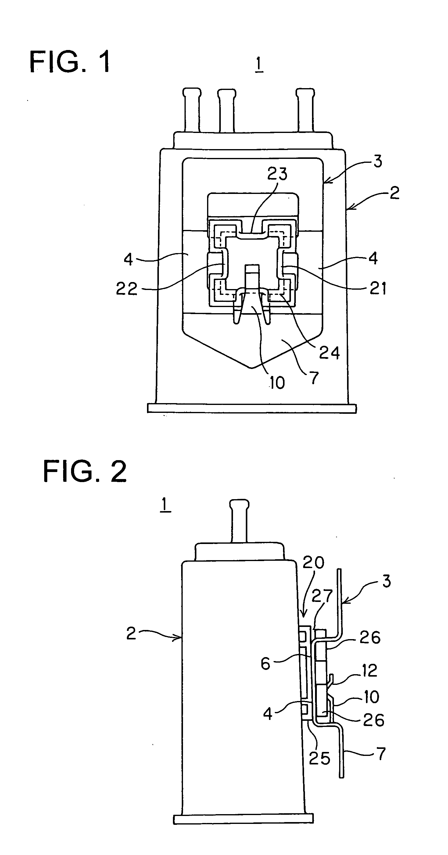
[0035]FIGS. 1 and 2 shows a case 2 of a canister 1 to which a case holding mechanism according to the first embodiment of the present invention is mounted, and as shown in FIGS. 1 and 2, the case holding mechanism includes a member 20 to be held formed on the side surface of the case 2 and a holding member 3 holding the member 20 to be held (the member to be held may be described as “hold member” or “held member” hereinafter).

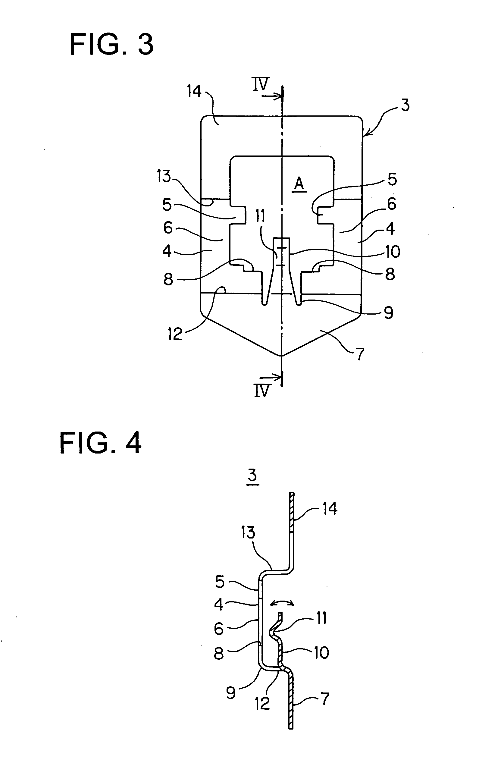
[0036] The holding member 3 will be described hereunder in detail with reference to FIGS. 3 and 4.

[0037] The holding member 3 is formed through punching working and bending working from a plate member so as to provide with a base portion 7, a ...


PUM


Abstract

A case holding mechanism includes a holding member and a member to be held thereby, one being mounted to the case and another to a body to which the case is to be held. The member to be held includes a first pair of parallel guide portions and another pair of parallel guide portions perpendicular to the one paired guide portions. The holding member disposed to be movable with respect to the guide portions therealong in a state restricted in thickness direction of the guide portions and adapted to hold the member to be held. The holding member includes a pair of slide portions slidable along outer surfaces of one paired guide portions, a lock portion extending between the paired slide portions in parallel with the one paired guide portions and engaged with the other paired guide portions, and a base portion connecting the slide portions and the lock portion.

Description

BACKGROUND OF THE INVENTION [0001] 1. Field of The Invention [0002] The present invention relates to a case holding mechanism or structure for holding a case of such as canister to a predetermined position. [0003] 2. Prior Art [0004] A machinery or equipment such as canister or reserve tank having a case is mounted detachably to a vehicle body by holding a hold member to be held, which is provided for one of the case and the vehicle body, to a holding member, which is provided for the other one thereof. Such mechanism is generally mounted in an engine room of a vehicle or a portion near a fuel tank, for example. [0005] In recent years, according to an increased requirement of high performance of vehicles such as automobiles, various machineries or equipments are accommodated and arranged in an engine room, and hence, a space for mounting a case of such as canister has been reduced therein. Accordingly, it has been desired to provide an improved mechanism for holding or mounting the ...

Claims


Application Information

Patent Timeline
Patent Type & Authority Applications(United States)
IPC IPC(8): B60R7/00B60R9/00B60R11/00
CPCB60R11/00B60R5/04
Inventor OHSAWA, HIROYASUMATSUURA, KAZUYASAKAGAMI, TAKASHIIKUMA, KOUICHI
Owner TOYO ROKI MFG CO LTD
Why Eureka
Try Eureka