Water-hydraulic machine

a water-hydraulic machine and water pump technology, applied in the direction of liquid fuel engines, engines with rotating cylinders, coatings, etc., can solve the problems of minor wear of the layer, hardly anticipated improvement, and astonishing carbon-containing layers

Inactive Publication Date: 2007-03-13
DANFOSS AS
View PDF17 Cites 16 Cited by
  • Summary
  • Abstract
  • Description
  • Claims
  • Application Information

AI Technical Summary

Benefits of technology

[0020]Finally, it is preferred that one of the two parts is a pressure plate, which is arranged between a control plate, being the other of the two parts, and the cylinder drum, and which turns during operation together with the cylinder drum in relation to the control plate, the control plate being provided with the plastics material and the pressure plate having the layer. Also in this area substantial loads occur, which can be absorbed by the DLC-layer, when demineralised water is used as hydraulic fluid, without causing any deterioration of the working characteristics of the machine.
[0021]Preferably, the sliding shoe is connected with the piston via a ball joint, and, at least in the area of the ball joint...

Problems solved by technology

In connection with demineralised water, the use of such carbon-containing layers leads to astonishing results.
At the same time, a mutual movement of the two parts will cause a minor wear away o...

Method used


Image

  • Water-hydraulic machine
  • Water-hydraulic machine
  • Water-hydraulic machine

Examples


Embodiment Construction

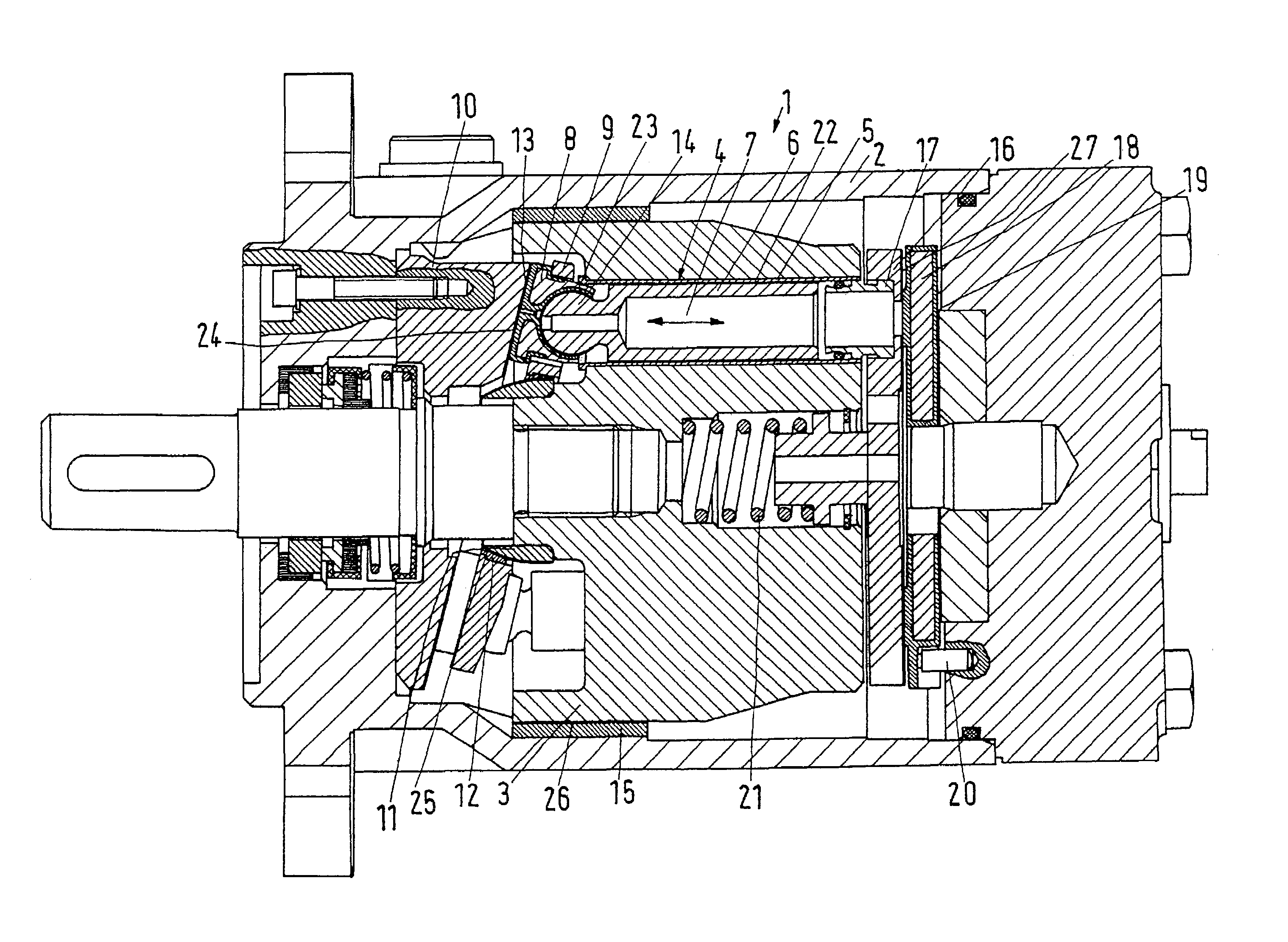
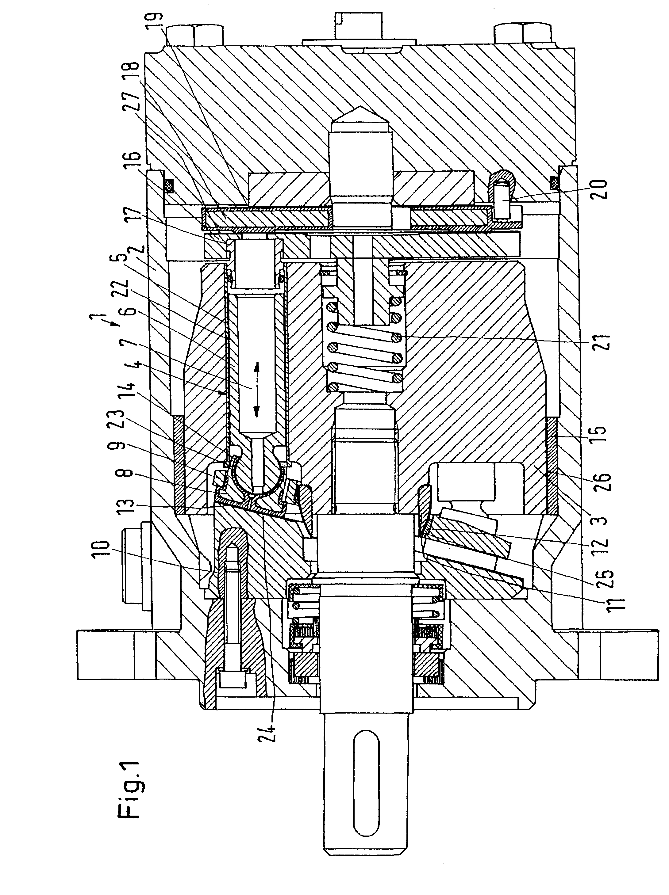
[0027]FIG. 1 shows a water-hydraulic machine 1 with a housing 2, in which a cylinder drum 3 is arranged to be rotatable.

[0028]In the cylinder drum 3 is arranged at least one cylinder 4, which is surfaced with a sleeve 5. The sleeve 5 is made of a plastics material from the group of high-performance thermoplastic plastics materials on the basis of polyarylether ketones, in the present case polyetherether ketones (PEEK). PEEK cooperates in a low-friction manner with the material of a piston 6, which is in the present case made of stainless steel.

[0029]The piston 6 is movable in the cylinder drum in the direction of a double arrow 7. The control of the piston 6 movements in the cylinder 4 occurs by means of a sliding shoe 8, which is held against a swashplate 10 by the effect of a holddown plate 9.

[0030]The holddown plate 9 is supported on the cylinder drum 3 via a ball joint with one ball 11. The ball 11 is also made of stainless steel. In the contact area with the ball 11, the holddo...


PUM

PropertyMeasurementUnit
Fractionaaaaaaaaaa
Fractionaaaaaaaaaa
Thicknessaaaaaaaaaa

Abstract

The invention concerns a water-hydraulic machine with at least two mutually movable parts, of which one has a surface of a plastic material with friction-reducing properties. In such a machine it is desired to enable the use of demineralised water. For this purpose, it is ensured that a layer of a carbon-containing material is arranged between the plastics material and the other part.

Description

CROSS-REFERENCE TO RELATED APPLICATIONS[0001]This application is entitled to the benefit of and incorporates by reference essential subject matter disclosed in German Patent Application No. 102 23 844.8 filed on May 28, 2002.FIELD OF THE INVENTION[0002]The invention concerns a water-hydraulic machine with at least two mutually movable parts, of which one has a surface of a plastic material with friction-reducing properties.BACKGROUND OF THE INVENTION[0003]A water-hydraulic machine of this kind is known from the “Nessie” project of Danfoss A / S, Nordborg, Denmark. An example of a publication of such a machine exists in DE 43 01 124 A1.[0004]In a water-hydraulic machine, water is used as a hydraulic medium. Compared with the normally used hydraulic oils, water has the advantage that leakages causes practically no pollution of the environment.[0005]However, water has the disadvantage that, contrary to oil, it has no lubricating properties. In a water-hydraulic machine, this usually lead...

Claims


Application Information

Patent Timeline
IPC IPC(8): F01B3/02F04B1/20F04B1/12F04B1/22F04B53/00F04B53/16F04B53/18F16C11/06F16J1/01F16J10/00
CPCF04B1/124F04B1/2035F04B53/166F05C2253/12F05C2203/0882F05C2225/12
Inventor HANSEN, OVE THORBOLOLSEN, PALLEMARTENSEN, LARSHAUGAARD, ERIK
Owner DANFOSS AS
Why Eureka
Try Eureka