Fluid operated contractile drive

Inactive Publication Date: 2007-05-29
FESTO AG & CO KG
View PDF8 Cites 3 Cited by
  • Summary
  • Abstract
  • Description
  • Claims
  • Application Information

AI Technical Summary

Benefits of technology

[0013]Preferably the respective head piece is provided with holding means serving to load the two clamping units to maintain a basic clamping effect on the contractile hose irrespectively of the fluid actuating effect in the inner space of the hose. The holding means may for example be in the form of a screw connection, which is provided between a clamping nut and the force output part of the first clamping unit.
[0014]A particularly compact arrangement is produced if the loading means responsible for the active clamping effect of the contractile hose are located in a region which is with

Problems solved by technology

In the case of the known contractile drive there was the problem that owing to its liability to deformation the contractile hose could be pulle

Method used


Image

  • Fluid operated contractile drive
  • Fluid operated contractile drive

Examples


Example

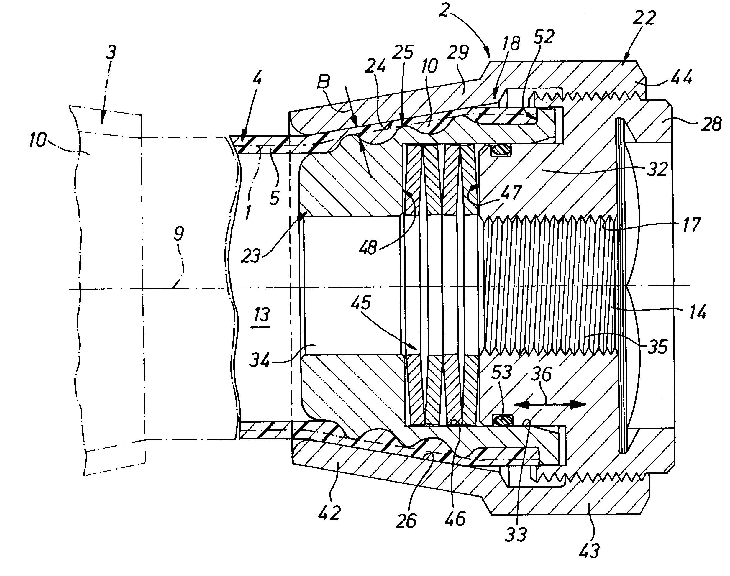
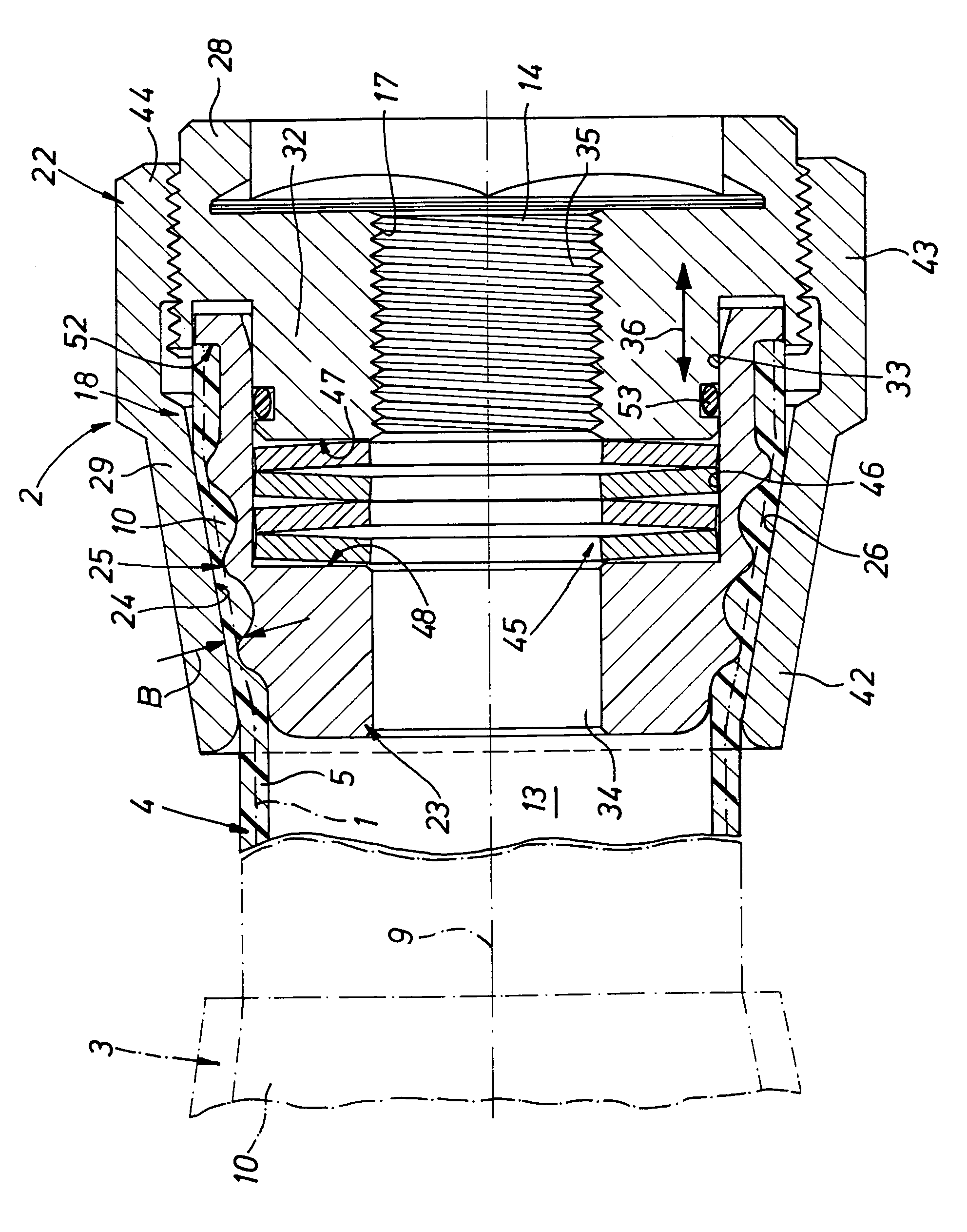
[0018]The contractile drive illustrated comprises the two (first and second) spaced apart head pieces 2 and 3, only one head piece 2 being illustrated completely in order to make the drawing more straightforward.

[0019]The two head pieces 2 and 3 are connected with each other by way of a contractile hose 4. At least in the non-activated state of the contractile drive the contractile hose 4 possesses a cylindrical tubular configuration. The longitudinal axis of the contractile drive, which at the same time represents the longitudinal axis of the contractile hose 4, is indicated at 9.

[0020]The contractile hose 4 possesses an elongated hose body 5 preferably manufactured of a material having rubber-like properties. As a material use is preferably made of rubber or an elastomeric material having similar properties. A strand structure1, only indicated in the drawing in chained lines, is embedded in the material of the hose body 5 and such structure is preferably completely surrounded by t...


PUM

PropertyMeasurementUnit
Lengthaaaaaaaaaa
Forceaaaaaaaaaa
Widthaaaaaaaaaa

Abstract

A fluid operated contractile drive which has a contractile hose (4) extending between two head pieces (2 and 3), and attached to at least one head piece (2 and 3) by having its respective end section (10) clamped in an annular clamping gap (26) defined between clamping surfaces (24 and 25), extending in an at least partially inclined manner in relation to the longitudinal axis (9) of the contractile hose (4) of a first clamping unit (22) having a force output means (17) serving for external force output and a second clamping unit (23) able to be shifted axially in relation to the first clamping unit. In addition to the contractile hose (4) between the two clamping unit (22 and 23) there are loading means (45), effective between same, such loading means (45) acting on the clamping unit (22 and 23) to produce a reduction of the width of the clamping gap (26).

Description

[0001]This application claims priority based on an International Application filed under the Patent Cooperation Treaty, PCT / EP03 / 01781, filed on Feb. 21, 2003, and German Patent Application No. DE 202 05 719.4, filed on Apr. 11, 2002.FIELD OF THE INVENTION[0002]The invention relates to a fluid operated contractile drive comprising a contractile hose extending between two head pieces, and contracting longitudinally when its internal hose space defined by it is acted upon by fluid pressure to exert axial tension forces on the head pieces drawing them together, the contractile hose being attached to at least one head piece by having its respective end section clamped in an annular clamping gap defined between clamping surfaces, extending at least partially inclined in relation to the longitudinal axis of the contractile hose and of a first clamping unit having a force output means serving for external force output and a second clamping unit able to be shifted axially in relation to the...

Claims


Application Information

Patent Timeline
IPC IPC(8): F16L47/00F15B15/10
CPCF15B15/103
Inventor SCHWARZ, STEFANLORENZ, BERND
Owner FESTO AG & CO KG
Why Eureka
Try Eureka