Power line repeater system and method

a power line repeater and power line technology, applied in repeater/relay circuits, frequency-division multiplexes, transmission monitoring, etc., can solve the problems of limiting the strength of data signals that can be injected onto power lines, overhead power lines are not designed to provide high-speed data communication, and are very susceptible to interferen

Inactive Publication Date: 2007-05-29
CURRENT TECH
View PDF159 Cites 259 Cited by
  • Summary
  • Abstract
  • Description
  • Claims
  • Application Information

AI Technical Summary

Problems solved by technology

While the concept may sound simple, there are many challenges to overcome in order to use power lines for data communication.
Overhead power lines are not designed to provide high speed data communications and are very susceptible to interference.
Additionally, federal regulations limit the amount of radiated energy of a power line communication system, which therefore limits the strength of the data signal that can be injected onto power lines (especially overhead power lines).
Consequently, due to the attenuation of the power lines, communications signals typically will travel only a relatively short distance on power lines.
Power system transformers are one obstacle to using power distribution lines for data communication.
As such, power line communication systems face the challenge of communicating the data signals around, or through, the distribution transformers.
In addition, power lines are susceptible to ingress noise, which may vary from location to location.
As a result, layout and network planning of a power line communications system may be difficult due to the unpredictability of the power line communications channels.

Method used


Image

  • Power line repeater system and method
  • Power line repeater system and method
  • Power line repeater system and method

Examples


example embodiment

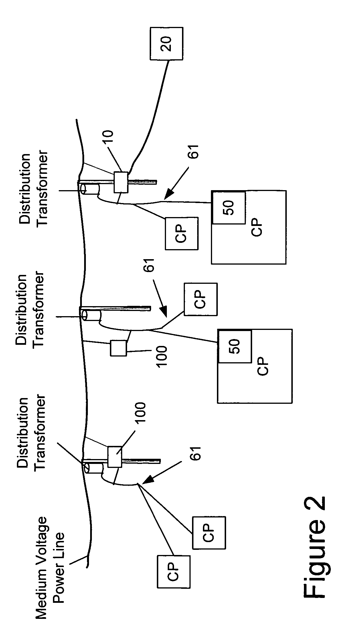
[0043]This example embodiment of the present invention includes a BD that also can be configured to repeat communications. The repeating functionality of the device allows the MCD or communications range of a BP 10 to be expanded such that communications devices (e.g., BDs 100) with unsatisfactory connectivity (e.g., due to noise or attenuation of signals) can be improved by repeating to make their connections satisfactory. In addition, the repeater functionality typically will extend the ‘reach’ of the BP 10 to include communications devices at distances that normally could not be reached by direct transmission between the device and the BP 10. Because the repeating BD 100 reduces the number of BPs 10 needed to be deployed to cover the geographical area of a PLCS, it also reduces the amount of backhaul media (e.g., fiber optic cable or wireless links) that needs to be deployed, thereby providing a significant economic improvement to the PLCS.

[0044]In this embodiment, a single devic...

example bd

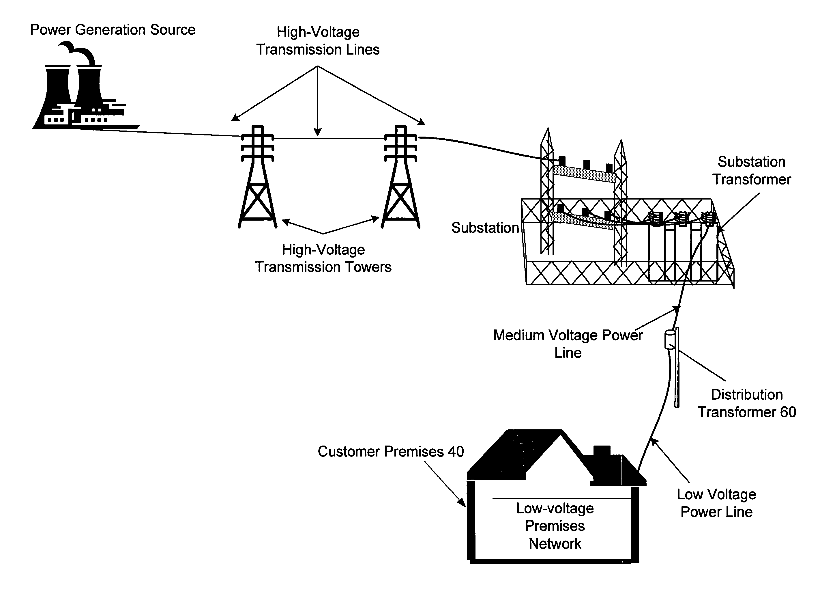
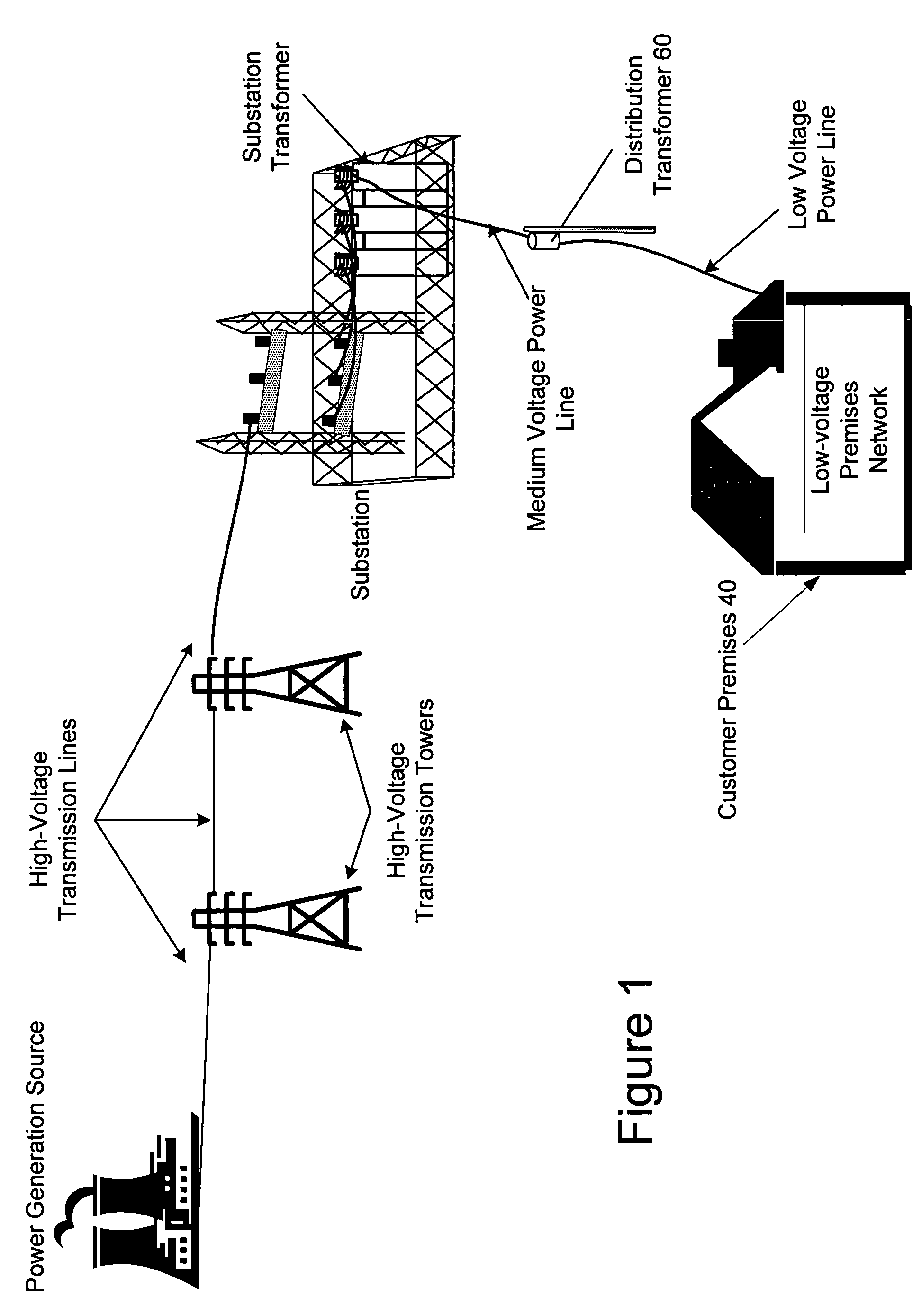
[0151]Path from MV Power Line to LV Power Line

[0152]MV Modem

[0153]The MV modem 280 receives the output of the first MV signal conditioner 260. The MV modem 280 and LV modem 450 provide a bi-directional path and form part of the MV to LV path and the LV to MV path. The components of the MV modem 280 have been described above in the context of the LV to MV path and are therefore not repeated here. The incoming signal is supplied to the ADC to convert the incoming analog signal to a digital signal. The digital signal is then demodulated. The modem then provides decryption, source decoding, error decoding, and channel decoding all of which are known in the art and, therefore, not explained in detail here.

[0154]The MV modem 280 also provides MAC processing through the use of MAC addresses. In one embodiment employing the present invention, the MAC address is used to direct data packets to the appropriate device. The MAC addresses provide a unique identifier for each device on the PLC net...


PUM


Abstract

A PLCS network element that provides communications to one or more user devices and may also repeat data for other network elements is provided. In one embodiment, the device includes software for discovering its upstream gateway, for acting as a gateway for other devices, and for relaying DHCP transmissions. In addition, the device includes software for receiving and processing commands from a remote computer system that may include commands enabling and disabling the repeater functionality. Finally, the device may also include software for receiving and processing configuration information that may include, for example, information of the other network devices for which it will repeat.

Description

CROSS-REFERENCE TO RELATED APPLICATIONS[0001]This application is a continuation-in-part and claims priority under 35 U.S.C. § 120 to U.S. patent application Ser. No. 10 / 315,725 filed Dec. 10, 2002, issued as U.S. Pat. No. 6,998,962; and this application is a continuation-in-part and claims priority under 35 U.S.C. § 119(e) to U.S. Provisional Patent Application Ser. No. 60 / 633,737 filed Dec. 6, 2004, both of which are incorporated herein by reference in their entirety.FIELD OF THE INVENTION[0002]The present invention generally relates to data communications over a power distribution system and more particularly, to a system that employs repeating communications over power lines and a method of using the same.BACKGROUND OF THE INVENTION[0003]Well-established power distribution systems exist throughout most of the United States, and other countries, which provide power to customers via power lines. With some modification, the infrastructure of the existing power distribution systems c...

Claims


Application Information

Patent Timeline
Patent Type & Authority Patents(United States)
IPC IPC(8): G08B1/08H04B1/38H04M11/04H04B3/54H04B3/56
CPCH04B3/54H04B3/56H04B3/58H04B2203/5441H04B2203/5466H04B2203/5487
Inventor WHITE, II, MELVIN JOSEPHTRAN, HENRY NGUYENFILEMYR, ALICE SHIRLEYKEHN, ROBERT DOUGLAS
Owner CURRENT TECH
Why Eureka
Try Eureka