Assembly tool for modular implants and associated method

a technology of modular implants and assembly tools, applied in the field of orthopaedic implants, can solve the problems of difficult positioning of the upper portion and hence the head of the prosthesis, the use of a one-piece prosthesis, and the locking of the components relative to one another, so as to achieve simple optimum ergonomics, facilitate gripping, and limit the displacement of the instrument

Inactive Publication Date: 2007-11-20
DEPUY PROD INC
View PDF296 Cites 54 Cited by
  • Summary
  • Abstract
  • Description
  • Claims
  • Application Information

AI Technical Summary

Benefits of technology

[0022]Another technical advantage of the present invention is the ability of the device to provide for optimum ergonomics. For example, according to one aspect of the present invention, the device is held and actuated by opposed extending handles which may be easily gripped by the surgeon and rotated relative to each other to secure the joint. Thus, the present invention provides for simple optimum ergonomics.
[0023]Yet another technical advantage of the present invention includes the ability of the device to provide for a measurement of forces in addition to the measurement of displacement. Due to frictional forces and additional complications, displacements of the device do not always directly lineally correspond to the forces that may be applied by the device. Therefore, there is an advantage to be able to measure the force applied by the device in addition to the displacement of the device. For example, according to another aspect of the present invention, a handle of the device may include a torque measuring feature which may be used to measure the torque applied to the device. Alternatively or in addition thereto, the device may include a force washer or other force transducers along the axial body of the instrument in order that the forces applied may be directly measured.
[0024]Another technical advantage of the present invention includes the ability of the device to limit the displacement of the instrument and therefore to limit the force applied to the prosthesis. If excessive force is applied to the prosthesis it is possible to overtighten and damage the component. For example, according to one aspect of the present invention, the displacement is physically limited by a helical opening of limited length or by a limited amount of threaded engagement between the two components. It is also possible to provide for a device with a break-away torque limiter that limits the amount of torque that the device may apply. Thus, the present invention provides for an ability to avoid overtightening of the prosthesis components.
[0025]Another technical advantage of the present invention is its simple and inexpensive design. For example, according to one aspect of the present invention, the device includes a cylindrical tube and a rod which slidably fits within the cylindrical tube. The tube and rod are threadably connected so that when one component is rotated with respect to the other one, the one component moves axially relative to the other one providing for a simple, inexpensive way of utilizing a device to disassemble or assemble a component.
[0026]An additional advantage of the present invention includes the ability of the device to be utilized simply and easily to disconnect as well as to connect the components of a modular prosthesis. For example, according to one aspect of the present invention, a component may be placed onto the assembly device to provide for connecting features to disassemble the device. Thus, the present invention provides for a simple and quick way of being utilized to disassemble as well as to assemble a prosthesis.
[0027]Other technical advantages of the present invention will be readily apparent to one skilled in the art from the following figures, descriptions and claims.

Problems solved by technology

Such a need for prostheses of varying shapes and sizes thus creates a number of problems in regard to the use of a one-piece prosthesis.
Moreover, since the bow of the stem must conform to the bow of the intramedullary canal of the patient's femur rotational positioning of the upper portion of the prosthesis is limited thereby rendering precise location of the upper portion and hence the head of the prosthesis very difficult.
Such a design allows the distal stem component to be selected and thereafter implanted in the patient's bone in a position which conforms to the patient's anatomy while also allowing for a limited degree of independent positioning of the proximal neck component relative to the patient's pelvis.
One issue that arises as a result of the use of a modular prosthesis is the locking of the components relative to one another.
The need for the firm locking is particularly necessary if the design does not provide for positive locking with weight bearing.
Current attempts to provide a device to adjoin components of a modular joint prosthesis are fraught with several problems.
For example, the device may not provide sufficient mechanical advantage to securely lock the components.
Further, the ergonomics available to lock the components may not be optimal.
Further, a device relying solely on the displacement for a taper connection may not provide sufficient force as there may not be an accurate correspondence of displacement to the clamping force.
Further, utilizing a displacement method may make it possible to overtighten and damage the components.
Further, prior art solutions may be difficult to manufacture or expensive to make.
Further prior art devices may be unsuitable for disconnecting the components.

Method used


Image

  • Assembly tool for modular implants and associated method
  • Assembly tool for modular implants and associated method
  • Assembly tool for modular implants and associated method

Examples


Embodiment Construction

[0059]Embodiments of the present invention and the advantages thereof are best understood by referring to the following descriptions and drawings, wherein like numerals are used for like and corresponding parts of the drawings.

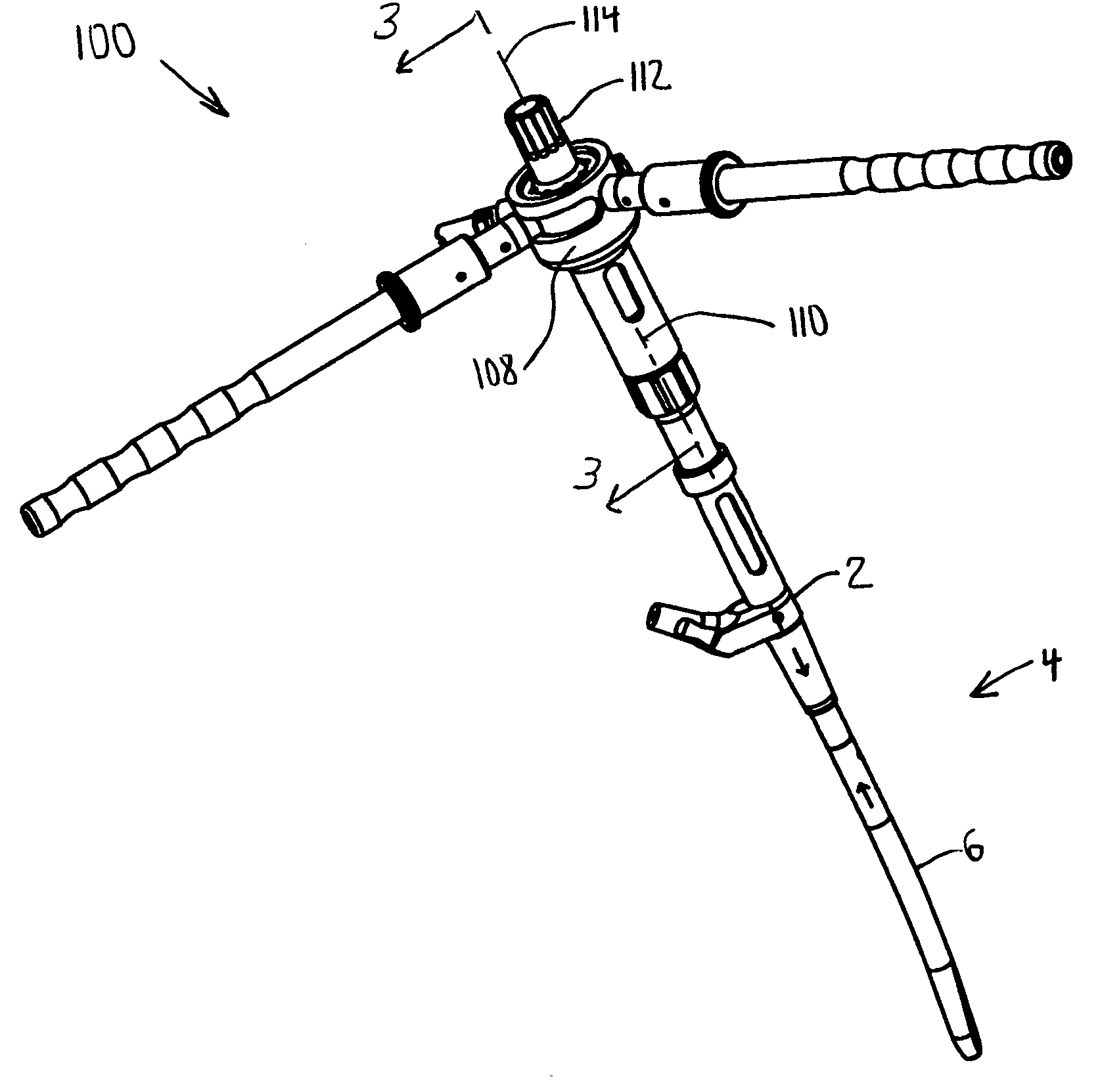
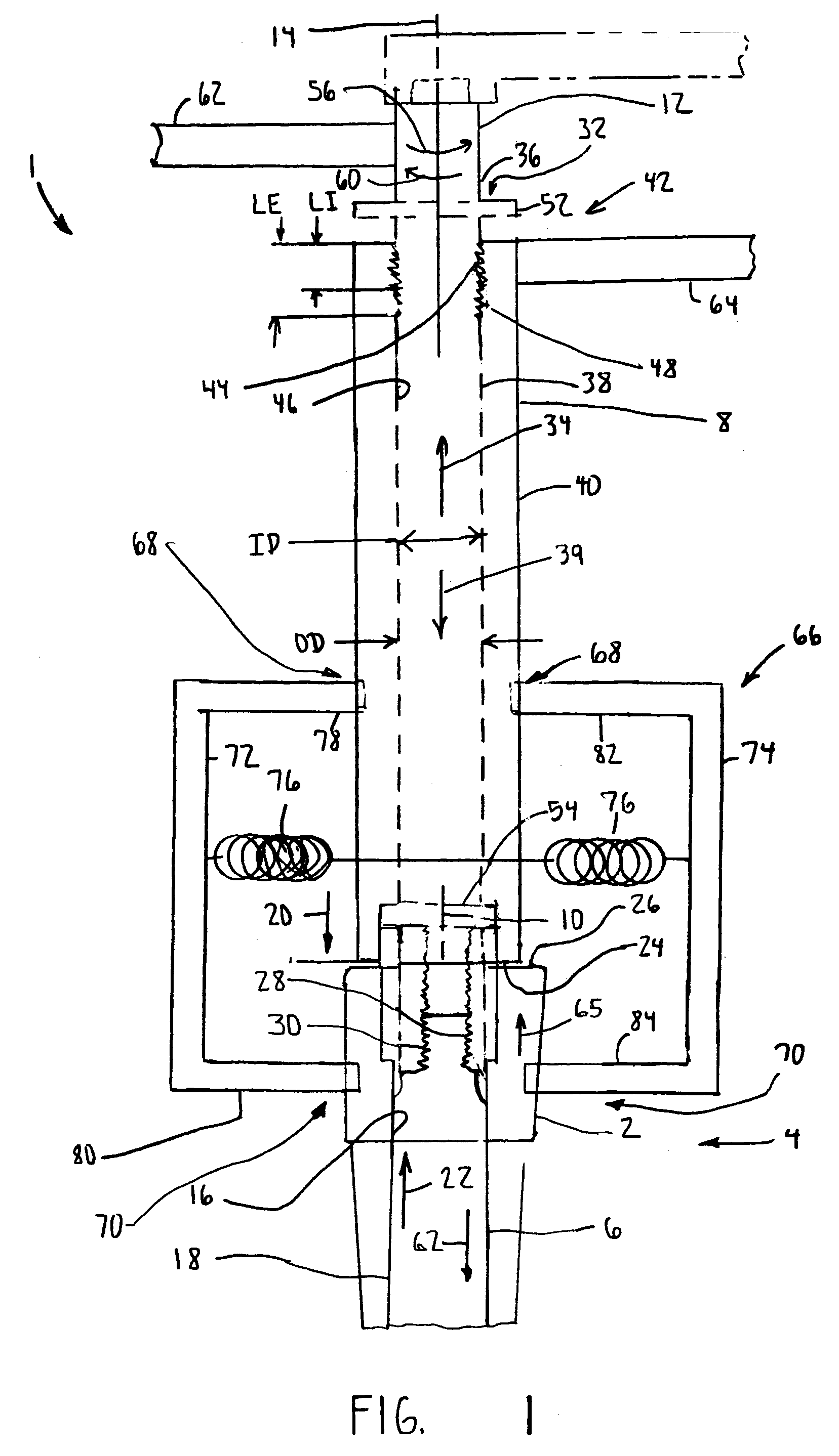
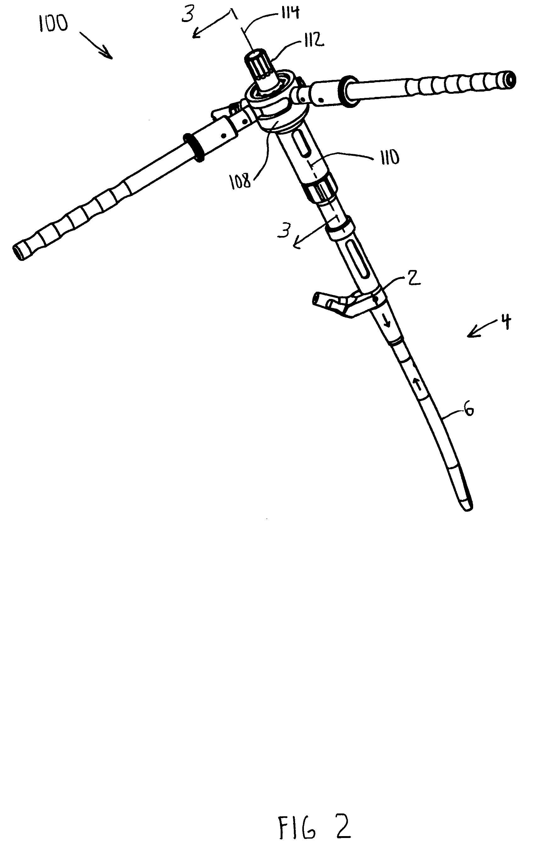
[0060]According to the present invention and referring now to FIG. 1, assembly tool 1 according to the present invention is shown. The assembly tool 1 is used for assembly of a first component 2 of a prosthesis 4 to a second component 6 of the prosthesis 4 for use in joint arthroplasty. The tool 1 includes a first member 8 operably associated with the second component 6. The first member 8 defines a first member longitudinal axis 10 of the first member 8. The tool 1 also includes a second member 12 operably associated with the second component 6. The second member 12 defines a second member longitudinal axis 14 of the second member 12. The second member 12 is adapted to provide relative motion of the second member 12 with respect to the first member 8 when the...


PUM


Abstract

An assembly tool (1) for assembly of a first component (2) of a prosthesis (4) to a second component (6) of the prosthesis (4) for use in joint arthroplasty is provided. The tool (1) includes a first member (8) operably associated with the first component (2). The first member (8) defines a first member longitudinal axis (10) of the first member (8). The tool also includes a second member (12) operably associated with the second component (6). The second member (12) defines a second member longitudinal axis (14) of the second member (12). The second member (12) is adapted to provide relative motion of the second member (12) with respect to the first member (8) when the second member (12) is rotated relative to the first member (8) about the second member longitudinal axis (14).

Description

CROSS-REFERENCE TO RELATED APPLICATIONS[0001]Cross reference is made to the following applications: U.S. patent application Ser. No. 10 / 606,303 entitled “MODULAR TAPERED REAMER FOR BONE PREPARATION AND ASSOCIATED METHOD”, and U.S. patent application Ser. No., 10 / 606,304 entitled “NON-LINEAR REAMER FOR BONE PREPARATION AND ASSOCIATED METHOD” filed concurrently herewith which are incorporated herein by reference.TECHNICAL FIELD OF THE INVENTION[0002]The present invention relates generally to the field of orthopaedics, and more particularly, to an implant for use in arthroplasty.BACKGROUND OF THE INVENTION[0003]Patients who suffer from the pain and immobility caused by osteoarthritis and rheumatoid arthritis have an option of joint replacement surgery. Joint replacement surgery is quite common and enables many individuals to function properly when it would not be otherwise possible to do so. Artificial joints are usually comprised of metal, ceramic and / or plastic components that are fi...

Claims


Application Information

Patent Timeline
Patent Type & Authority Patents(United States)
IPC IPC(8): A61F2/36A61B17/56A61F2/00A61F2/32A61F2/46
CPCA61F2/36A61F2/4637A61F2250/0058A61F2002/30535
Inventor DWYER, KIMBERLY ANNDANIELS, DAVID WAYNEPARKER, BRAD ALAN
Owner DEPUY PROD INC
Why Eureka
Try Eureka