Photocatalytic process

a photocatalytic and cleaning technology, applied in the direction of physical/chemical process catalysts, disinfection, water treatment compounds, etc., can solve the problems of mercury lamps that take a long time to fully power up, contaminate these systems with toxic mercury, and cause environmental and human harm

Inactive Publication Date: 2007-11-27
APPLIED NANOTECH HLDG
View PDF4 Cites 22 Cited by
  • Summary
  • Abstract
  • Description
  • Claims
  • Application Information

AI Technical Summary

Problems solved by technology

There are several problems with these UV light sources.
They often contain mercury and are thus toxic to the environment and to humans since they are often disposed in a landfill.
Mercury lamps also take some time to switch ON to full power, i.e., they have a warm-up period.
If the lamps break in the home air system or water supply, they will contaminate these systems with toxic mercury.
Further, the life of these systems is limited and the intensity of the UV light is weak, thus limiting the usefulness of the decontamination or cleaning system using the TiO2 photocatalyst.
Although LEDs have longer lifetimes and are instant ON, they are not efficient and do not illuminate uniformly.
This material is not conductive and may not be robust.

Method used


Image

  • Photocatalytic process
  • Photocatalytic process
  • Photocatalytic process

Examples


Embodiment Construction

[0015]In the following description, numerous specific details are set forth such as specific network configurations, etc. to provide a thorough understanding of the present invention. However, it will be obvious to those skilled in the art that the present invention may be practiced without such specific details. In other instances, well-known circuits have been shown in block diagram form in order not to obscure the present invention in unnecessary detail. For the most part, details concerning timing considerations and the like have been omitted inasmuch as such details are not necessary to obtain a complete understanding of the present invention and are within the skills of persons of ordinary skill in the relevant art.

[0016]Refer now to the drawings wherein depicted elements are not necessarily shown to scale and wherein like or similar elements are designated by the same reference numeral through the several views.

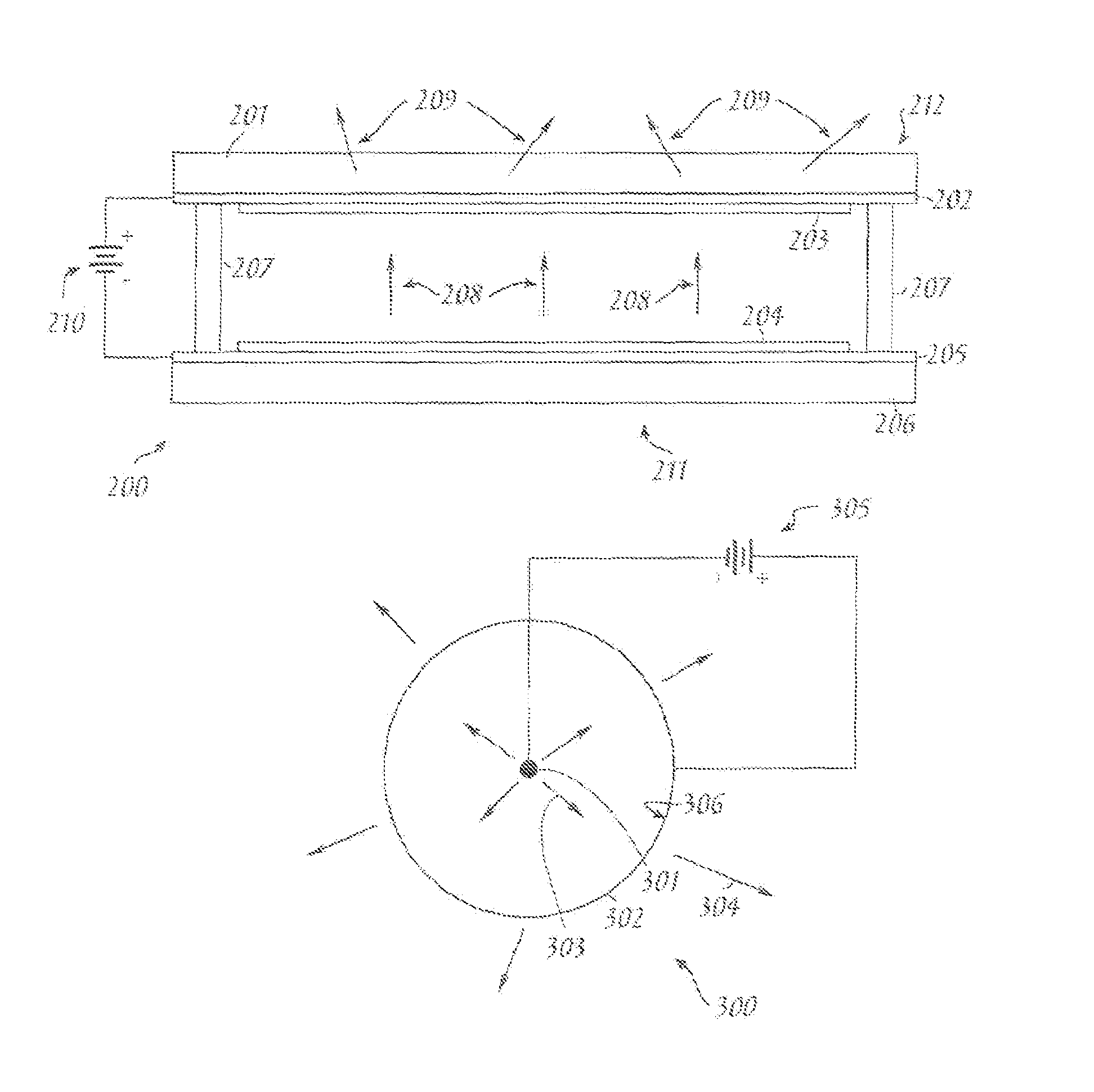
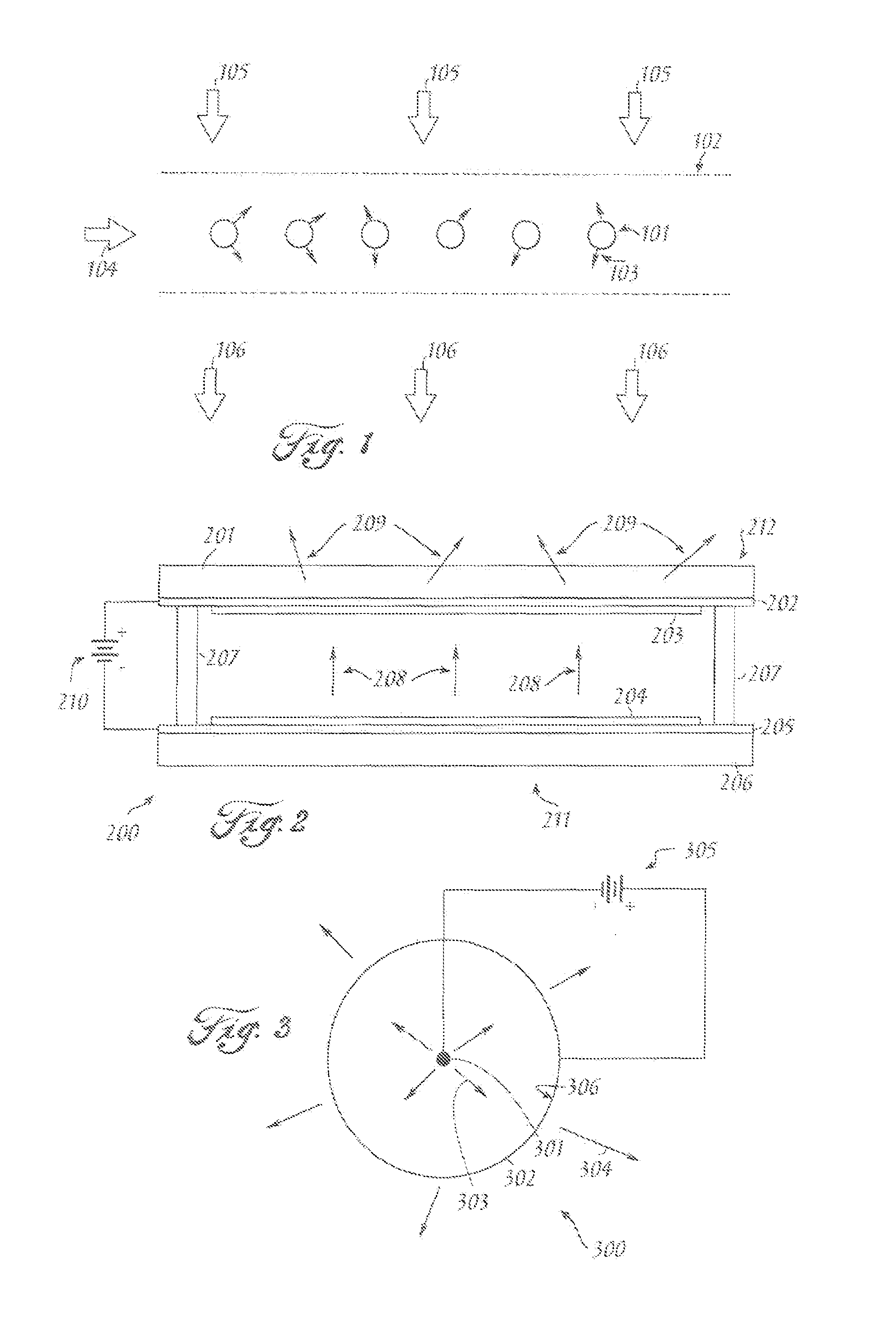
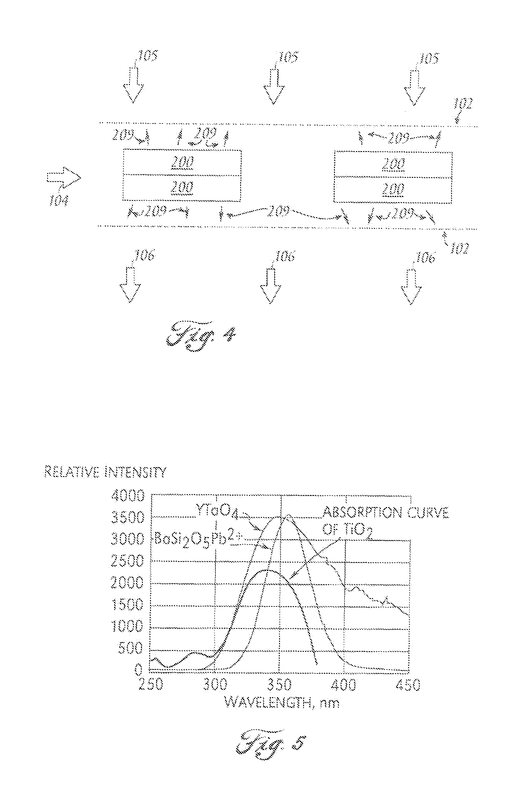
[0017]FIG. 1 illustrates a configuration of an air purification s...


PUM

PropertyMeasurementUnit
temperaturesaaaaaaaaaa
distanceaaaaaaaaaa
electric fieldaaaaaaaaaa

Abstract

A photocatalytic cleaner for air or water includes a photocatalytic material coating a substrate. An anode, positioned a predetermined distance from the substrate, includes a phosphor that emits ultraviolet light in response to bombardment by electrons from a field emission cathode emitting electrons in response to an electric field. The field emission cathode may be a carbon based field emitter material including incorporating carbon nanotubes.

Description

[0001]This application claims priority to U.S. Provisional Patent Application Ser. No. 60 / 624,724 filed Nov. 3, 2004.TECHNICAL FIELD[0002]The present invention relates in general to photocatalytic cleaners, and in particular, to a field emission device for implementing a photocatalytic air or water cleaner.BACKGROUND INFORMATION[0003]Titanium oxide has been used as a photocatalyst for many different applications. One of the most studied applications is for solar cell applications. There are many other applications that are already used in products. Titanium dioxide (TiO2) is used to absorb ultraviolet (UV) rays in sun screen lotions. TiO2 is also used to clean water and air in purification systems. The TiO2 works by creating free radicals and charged particles that will react with bio and viral contaminants and noxious chemicals near the activated TiO2, thus decomposing these contaminants into harmless compounds.[0004]In these purification systems, a UV light source is required to a...

Claims


Application Information

Patent Timeline
Patent Type & Authority Patents(United States)
IPC IPC(8): B01J19/08
CPCC02F1/32C02F1/725B82Y30/00B01D2255/40B01D2255/802B01J35/004C02F2305/10C02F2201/3222
Inventor YANIV, ZVIFINK, RICHARD LEE
Owner APPLIED NANOTECH HLDG
Why Eureka
Try Eureka