Trackball device

a trackball and device technology, applied in the field of trackball devices, can solve the problem of driving up the price of the devi

Inactive Publication Date: 2008-01-29
PANASONIC CORP
View PDF18 Cites 44 Cited by
  • Summary
  • Abstract
  • Description
  • Claims
  • Application Information

AI Technical Summary

Problems solved by technology

However, expensive Hall IC 120 drives up the price of the device.

Method used


Image

  • Trackball device
  • Trackball device
  • Trackball device

Examples


first exemplary embodiment

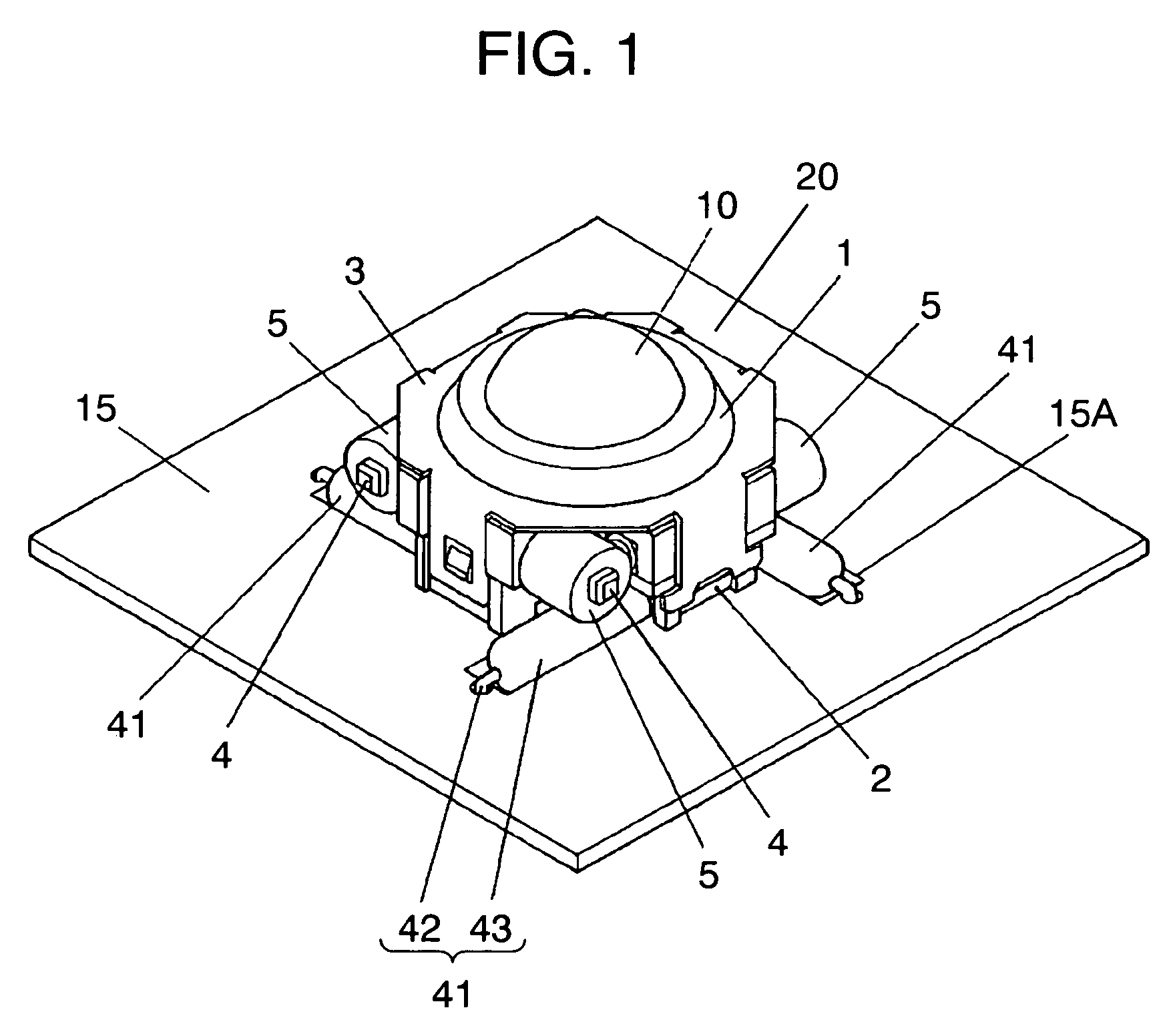
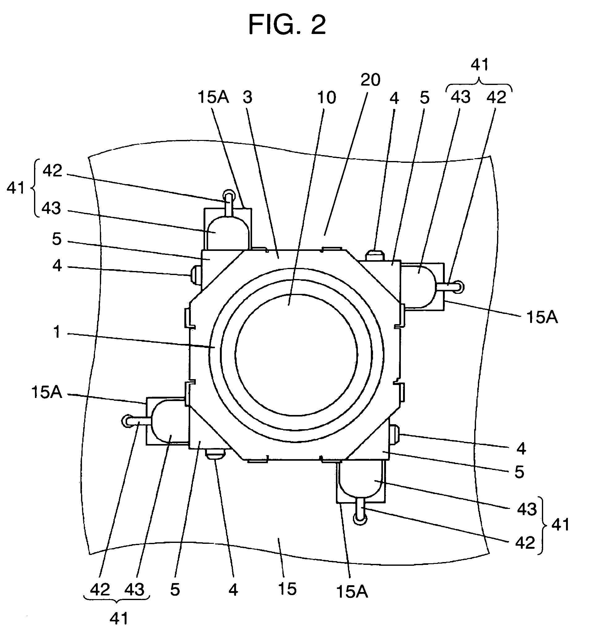
[0042]FIG. 1 is a perspective view of an appearance of a trackball device in the first exemplary embodiment of the present invention. FIG. 2 is a top view and FIG. 3 is a side view of the trackball device. FIG. 4 is a perspective view of the track ball device before assembling a mechanical structure and wiring board. FIG. 5 is a sectional view and FIG. 6 is an exploded perspective view of the mechanical structure.

[0043]As shown in FIGS. 1, 2, 3, and 4, the trackball device in the first exemplary embodiment includes operating ball 10, mechanical structure 20 (including upper case 1, base 2, cover 3, roller 4, and permanent magnet 5), and wiring board 15 (on which push switch 25 and reed switch 41 are mounted).

[0044]First, mechanical structure 20 of the present invention is described in detail with reference to FIGS. 5 and 6. Operating ball (hereafter “ball”) 10 is housed in an inner space formed by a roughly cross-shaped resin upper case 1 and also roughly cross-shaped resin base 2 l...

second exemplary embodiment

[0080]The second exemplary embodiment describes an example of another alignment of magnets and reed switches for applying a rotation-restricting force to the rollers described in the first exemplary embodiment. The same reed switches are used, but different reference marks are given for easier understanding. Other components same as those already described are given the same reference marks to omit duplicate description.

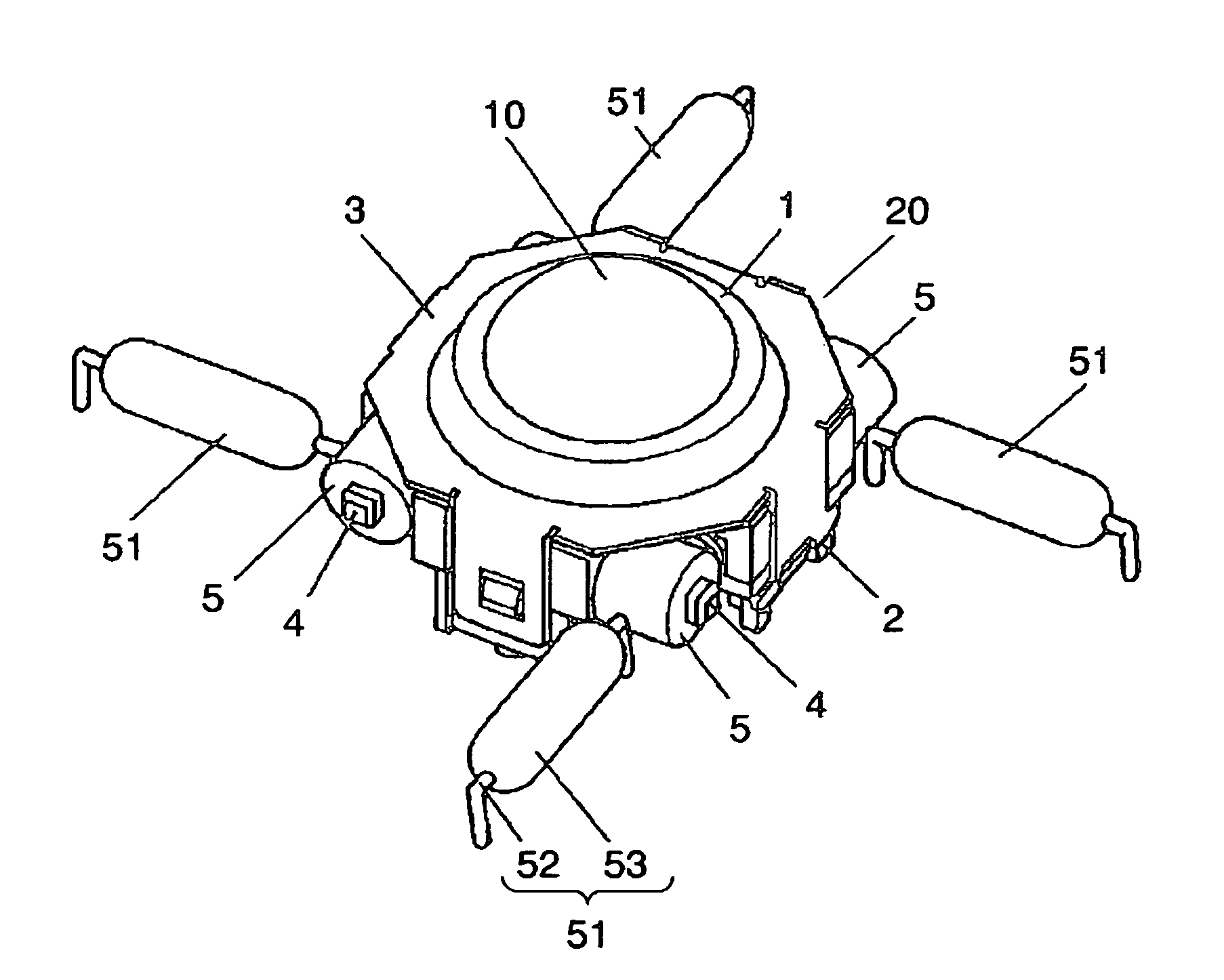
[0081]FIG. 12 is a perspective view of an appearance of a trackball device in the second exemplary embodiment of the present invention. FIG. 13 is a top view and FIG. 14 is a side view of the trackball device. As shown in the drawings, the trackball device in this exemplary embodiment has the same mechanical structure 20 as the first exemplary embodiment, and reed switches 51 are respectively disposed on a periphery of corresponding four rollers 4 with magnets 5 forming a rectangle.

[0082]In each reed switch 51, one lead-out portion of reed 52 led out linearly from th...


PUM


Abstract

A trackball device of the present invention includes an operating ball, multiple rollers which rotate by contacting the ball while it is rotated, multipole permanent magnets which co-rotate with these rollers, and a reed switch disposed in a position where it turns on and off as a result of changes in magnetic flux caused by the rotation of the permanent magnets so as to provide tactile feedback when the ball is rotated. The trackball device is configured to make an attractive force generated between the reed switch and permanent magnet affect the rotation of the rollers.

Description

FIELD OF THE INVENTION[0001]The present invention relates to trackball devices that act as input devices for electronic equipment which provide a range of input operations when the ball is moved in predetermined ways.BACKGROUND OF THE INVENTION[0002]Trackball devices are currently used for a range of input operations, and are often installed in electronic equipment.[0003]One of these conventional trackball devices is disclosed in Japanese Patent Unexamined Publication No. 2002-373055, and is described below with reference to drawings.[0004]FIG. 18 is a perspective view of the conventional trackball device before assembling a mechanical structure and a wiring board. FIG. 19 is a top view and FIG. 20 is a left side view of the trackball device.[0005]A flat part of metal cover 103 with a hole at its center is disposed on roughly cross-shaped resin upper case 101. This cover 103 has first legs 103A respectively hanging down from the first opposing sides of the flat part, and second legs...

Claims


Application Information

Patent Timeline
Patent Type & Authority Patents(United States)
IPC IPC(8): H01H9/00G06F3/0354
CPCG06F3/016G06F3/03549H01H36/0053
Inventor NAKA, YOSHIOYAMAMOTO, TAMOTSU
Owner PANASONIC CORP
Why Eureka
Try Eureka